Preface
What is this book about?
About 71% of Earth’s surface is covered with water, and about 97% of the water is in our oceans. Although the ocean plays a critical role in everything from the air we breathe to daily weather and climate patterns, we know very little about it. To really understand our oceans, we need a way to sense and observe the numerous complex processes that drive the ocean environment, and to report the data collected back to our data centers. While cabled ocean observatories have been established in a few locations, they are too expensive to setup and maintain for large scale data collection across the vast oceans.
Over the past few decades, wireless communication technology has percolated into every aspect of our lives, and we have come to take it for granted. This technology forms the bedrock of wireless sensor networks, allowing us to gather data with ease. Most of the wireless communication technology we use relies on electromagnetic waves (e.g. radio waves, visible light) that get rapidly absorbed by water. Hence the technology is ineffective for underwater communication, except at very short distances or extremely low data rates. Most underwater communication systems today use acoustic waves, which can travel long distances in the right conditions. At short distances in clear waters, optical communication systems are sometimes used for high speed communications. Although these communication technologies can be leveraged to establish point-to-point communication links, these links do not integrate well with networking technology available today.
The Unet project strives to develop technologies that allow us to build communication networks that extend underwater, be it via acoustic, optical, or even wired links. Some nodes in such networks may be above water, while others are underwater. In this handbook, we explore how to build such networks using UnetStack3 , an agent-based network technology that was developed in the Unet project.
Who should read this book?
This book is intended for readers interested in deploying networks that extend underwater, or developing technology or protocols for use in underwater networks. Part I of the book provides an overview, and is recommended for all readers. Part II is aimed at readers who wish to deploy and maintain networks that extend underwater. Part III is aimed at application developers and software engineers who wish to integrate with UnetStack-based networks. Parts IV and V dive deeper into UnetStack, and are intended for researchers and engineers who wish to develop, simulate and test novel underwater networking protocols.
The book assumes that readers have a basic understanding of traditional networking technology. While expert software development skills are not required to benefit from this book, familiarity with scripting or programming is essential. Readers with knowledge of Java, Groovy and/or Python will find it easy to follow the examples in the text, but even readers without prior knowledge of these languages should be able to pick up necessary skills along the way.
Part I: Introduction to UnetStack
1. Introduction
1.1. What is a Unet?
The Internet has changed our lives beyond anyone’s wildest expectations, fundamentally changing the way we interact, the way we learn, and the way we work. More recently, devices have started connecting to the Internet, and communicating with other devices. This Internet of Things (IoT) has the potential to have a huge impact on the way we understand our environment, and interact with it. Given that most of our planet’s surface is covered with water, would it then not make sense that at least some of these devices might be in water? Some devices might measure ocean temperature and acidification to give us a handle on climate change, while other devices might monitor fresh water quality to ensure safe drinking water for us. Autonomous underwater vehicles (AUVs) may patrol our coastal waters looking for intruders, or tracking down sources of pollution or nutients that encourage harmful algal blooms. Be it static sensors or mobile AUVs, we need a way to connect them into a network that we can communicate and interact with. The Unet project strives to develop technologies that allow us to do precisely this. In this handbook, we explore how to use UnetStack3 , a technology developed as part of the Unet project, to build communication networks that extend underwater.
Most wireless technologies today rely on electromagnetic waves that don’t propagate well underwater. Therefore, to extend IoT underwater, we typically need a mix of technologies — cabled links where possible, otherwise radio frequency (RF) wireless links above water, and mid-to-long range wireless acoustic or short-range wireless optical links underwater. A "Unet" network (which we will simply call Unet henceforth) consists of several nodes (underwater, on the surface of water, or above water) that communicate over various types of links, as shown in Figure 1 .
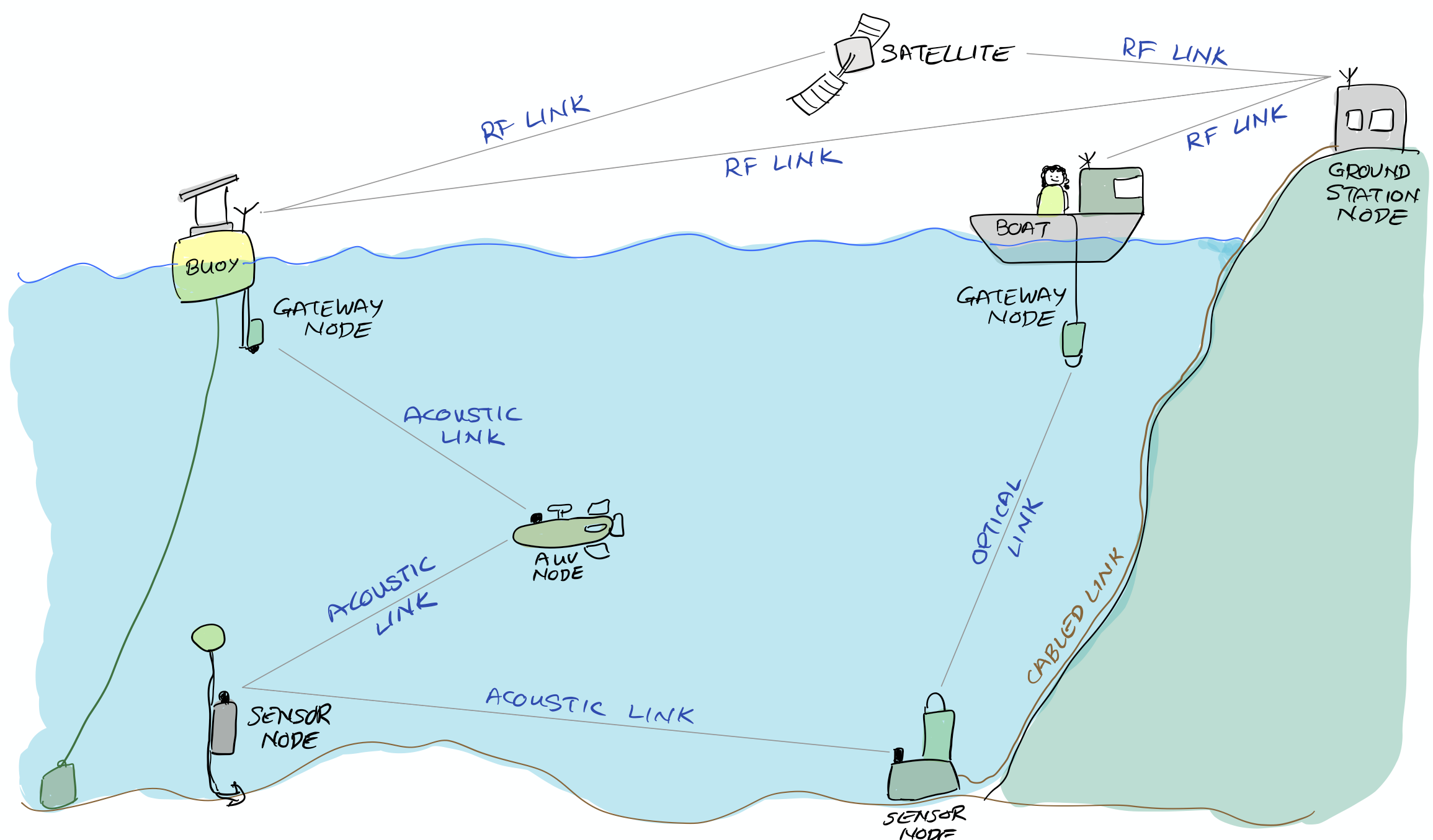
A Unet consists of many Unet nodes (e.g. underwater sensor nodes, Autonomous Underwater Vehicles (AUVs), gateway buoys, ground stations, boats/ships) that generate, consume or relay data over a variety of links:
-
Acoustic links are typically used for mid-to-long range communication underwater. These links usually offer low data rates and long propagation delay due to the slow speed of sound in water (as compared to EM waves).
-
Optical links are used for short range high data rate communications in water.
-
RF links are used for mid-range communication in air.
-
GSM links are used for near-shore connectivity through air.
-
Satellite links are used for nodes that are far out at sea, and cannot be reached through GSM or RF links. These links usually are expensive and offer relatively low data rates.
-
Wired links (Ethernet, serial, fiber optic) are used for long-term static deployments underwater, or over short distances where cabling is feasible.
-
In some cases, nodes are retreived and data is transferred from them to other nodes in the network on a regular basis, using physical media (e.g. USB drives, SD cards, etc). These links usually offer very high data rates, but are only available intermittently. We dub such links as Sneakernet links .
A link is simply a logical connection between two nodes, often provided by equipping both the nodes with modems. We summarize various types of links in Table 1 .
| Link type | Communication range # | Data rate # | Latency |
|---|---|---|---|
|
High-frequency acoustic (underwater) |
Short |
Medium |
milliseconds |
|
Mid-frequency acoustic (underwater) |
Medium |
Low |
seconds |
|
Low-frequency acoustic (underwater) |
Long |
Very low |
seconds |
|
Optical (underwater) |
Very short |
High |
Negligible |
|
RF (in air) |
Medium |
Medium |
Negligible |
|
GSM (in air, near shore) |
Medium |
Medium |
milliseconds |
|
Satellite (in air) |
Long |
Low |
milliseconds |
|
Wired/cabled |
Long (expensive) |
High |
Negligible |
|
Sneakernet |
Long (intermittent) |
Very high |
hours or days |
|
# Communication range and data rate vary substantially across devices and environments. Short range usually is in tens of meters, medium range is several km, and long range is typically tens of km. Low data rates are in hundreds of bps, medium data rates are in kbps, and high data rates are in Mbps. |
|||
1.2. UnetStack
Unet nodes are equipped with one or more network interfaces that allow communication over some of these links. For example, to communicate over an underwater acoustic link, we need an underwater acoustic modem . For an underwater optical link, we use an underwater optical modem . Most RF, GSM, satellite or wired links would be accessed over a standard TCP/IP network interface. In all cases, each Unet node would run the UnetStack software that allows us to effectively communicate over all of these types of links using a common Application Programming Interface (API). UnetStack API bindings are available for several languages including Java, Groovy, Python, Julia, C, Javascript, etc.
UnetStack has a several components, as depicted in Figure 2 :
-
The Unet framework provides core services, messages, agents and APIs needed by UnetStack.
-
The Unet basic stack is a collection of agents providing services and functionality required by typical Unets. These agents, together with the Unet framework, are sufficient to build fully functional Unets.
-
The Unet premium stack is a collection of agents providing advanced functionality and/or higher performance. Many of the premium agents provide similar services as the basic ones, but used advanced techniques for better performance and bandwidth efficiency.
-
The Unet simulator is able to simulate Unets with many nodes on a single computer. It can run in realtime simulation mode for interactive testing of agents and protocols, working to provide the user with the same user experience as in a real Unet. It can also be run in discrete event simulation mode to perform a large number of simulations in a short time, allowing Monte Carlo testing and performance evaluation of network protocols.
-
The Unet IDE is an integrated development environment (IDE) for developers to develop, simulate and test Unet agents and protocols. It also enables the developer to visualize and interact with simulated networks.
-
Unet audio is a soundcard-based realtime software defined open architecture acoustic modem (SDOAM) that runs on desktop, laptop or single-board computers, and can be used to build and test simple Unets. It is a great tool for not only developing and testing network protocols, but also developing acoustic communication techniques.
The components are packaged into various editions . The community edition is downloadable free of charge for educational and research purposes. It has all the components required to develop, simulate, test and deploy Unets. The commercial and OEM editions package offer advanced functionality, better performance and tighter integration with vendor-specific hardware.

In the next few chapters, we will learn how to use UnetStack and how to customize it to meet our networking needs. In some cases, it may be necessary to prototype and simulate a Unet before it is actually implemented. We will also learn how to do that using the Unet simulator.
2. Getting started
In this chapter, you will learn how to set up a simple 2-node underwater network with an acoustic link. If you already own a couple of UnetStack-compatible acoustic modems, you can certainly use them! And we’ll show you how to do that in Section 2.6 . But let us first start with a simulated 2-node underwater network, since all you need for this is a computer and the Unet simulator.
2.1. Setting up a simple simulated network
Download UnetStack community edition for your OS and untar/unzip it. Open a terminal window in the simulator’s root folder and start the simulator:
$ bin/unet samples/2-node-network.groovy

2-node network
--------------

Node A: tcp://localhost:1101, http://localhost:8081/
Node B: tcp://localhost:1102, http://localhost:8082/
If you’re using Windows, you may need to use:
bin\unet samples\handbook\2-node-network.groovy
|
Open two web browser windows and key in the two http URLs shown above in each browser. This should give you a command shell for node A and node B in the two browser windows.
2.2. Making your first transmission
On the command shell for node A, type:
> tell 0, 'hello!'
AGREE
Address 0 is a broadcast address, so you did not need to explicitly know the address of node B to transmit a message to it. After a short delay, you should see the message on the command shell for node B:
[232]: hello!Congratulations!!! You have successfully transmitted your first message over the Unet.
The
[232]
that you see on node B is the
from
address (of node A). The simulator automatically allocates addresses to each node. You can easily find out the addresses of both nodes (on either node):
> host('A')
232
> host('B')
31
You can try sending a message back from node B:
> tell 232, 'hi!'
and you should see the message
[31]: hi!
on node A after just a short delay.
You could have specified the hostname instead of the address when sending the message:
tell host('A'), 'hi!'
.
|
2.3. Propagation delay & ranging
In the simulation, nodes A and B are placed 1 km apart. Since the speed of sound in water is about 1500 m/s (exact sound speed depends on temperature, salinity and depth), the signals take about 0.7 s to travel between the simulated nodes. This explains the short delays you see between sending the message from one node and receiving it on the other. You can also make use of this time delay to measure the distance between the nodes!
On node A, type:
> range host('B')
999.99976
You got an estimate of 1000 m for the range between the two nodes.
2.4. Sending & receiving application data
In real applications, you may want to send complex datagrams (messages) programmatically between nodes. The simplest way to do this is via the UnetSocket API ( Chapter 9 ). Let’s try it!
On node B, type:
> s = new UnetSocket(this);              (1)
> rx = s.receive() (2)| 1 |
Open a socket on node B (
this
refers to node B, since you are typing this on node B’s command shell). The semicolon (";") at the end of the statement simply prevents the shell from printing the return value automatically.
|
| 2 | Receive a datagram. This call blocks until a datagram is available. |
On node A, type:
> s = new UnetSocket(this);
> s.send('hello!' as byte[], 0)          (1)
true
> s.close()| 1 |
Send 6 ASCII bytes ('hello!') to address 0 (broadcast address). The
as byte[]
is necessary in Groovy to convert the string you specified into a byte array that the
send()
method expects.
|
Node B will receive the bytes as a
RxFrameNtf
message. You can check the data in the received datagram on the command shell for node B, and close the socket:
RxFrameNtf:INFORM[type:DATA from:232 rxTime:4134355059 (6 bytes)]
> rx.data
[104, 101, 108, 108, 111, 33]            (1)
> new String(rx.data)                    (2)
hello!
> s.close()| 1 | These are the bytes representing the ASCII characters ['h', 'e', 'l', 'l', 'o', '!']. |
| 2 | This puts together the ASCII characters in the byte array into a String. |
While we demonstrated the use of the
UnetSocket
API in Groovy on the command shell, the same commands work in a Groovy script or application, with one minor modification. When the socket is opened, you will have to specify the connection details (such as host name or IP address, and the API port number) of the modem (or simulated modem) to connect to. For example, if UnetStack is running on
localhost
at port number 1101, you can connect to it using:
s = new UnetSocket('localhost', 1101);
|
2.5. Sending & receiving from a Python application
UnetStack provides API bindings for many languages (Java, Groovy, Python, Julia, C, Javascript, etc). We demonstrate the use of the Python API here, but the usage is quite similar in other languages too.
We’ll assume you have Python 3.x already installed. Let us start by installing the UnetStack Python API bindings:
$ pip install unetpy==3.1.2
Collecting unetpy==3.1.2
  Using cached unetpy-3.1.2-py3-none-any.whl.metadata (1.7 kB)
Collecting fjagepy>=1.7.2 (from unetpy==3.1.2)
  Using cached fjagepy-2.1.2-py3-none-any.whl.metadata (8.0 kB)
Collecting numpy>=1.11 (from unetpy==3.1.2)
  Using cached numpy-2.4.6-cp314-cp314-macosx_14_0_arm64.whl.metadata (6.6 kB)
Installing collected packages: numpy, fjagepy, unetpy
Successfully installed fjagepy-2.1.2 numpy-2.4.6 unetpy-3.1.2
We will now write
tx.py
and
rx.py
scripts to transmit and receive a datagram respectively. We assume that you have the two-node network setup from the previous section with node A and B available on
localhost
API port 1101 and 1102 respectively.
tx.py
from unetpy import UnetSocket

s = UnetSocket('localhost', 1101)                (1)
s.send('hello!', 0)                              (2)
s.close()| 1 |
Connect to node A (
localhost
API port 1101).
|
| 2 | Broadcast a 6-byte datagram. Address 0 is the broadcast address. |
rx.py
from unetpy import UnetSocket

s = UnetSocket('localhost', 1102)                               (1)
rx = s.receive()                                                (2)
print('from node', rx.from_, ':', bytearray(rx.data).decode())  (3)
s.close()| 1 |
Connect to node B (
localhost
API port 1102). Change the
localhost
to modem B’s IP address and port 1102 to port 1100, if you are working with a modem.
|
| 2 |
Blocking
receive()
will only return when a datagram is received or the socket is closed. If a datagram is received,
rx
will contain the notification message with the details of the datagram.
|
| 3 |
In Python
from
is a keyword and cannot be used as an field name. We therefore use
from_
for the source node address.
|
First run
python rx.py
to start reception. Then, on a separate terminal window, run
python tx.py
to initiate transmission. You should see the received datagram printed by the
rx.py
script:
$ python rx.py
from node 232 : hello!
Once you are done with your testing, it is time to shutdown the simulation. You can do that by pressing
Ctrl-C
on the terminal where you started the simulator. Alternatively, you can go to the shell of one of the nodes, and type:
shutdown
.
|
2.6. Using acoustic modems
So far, we have worked with a simulator. While the experience is similar, it is not exactly the same. There is no real substitute for working with real modems. If you happen to have two UnetStack-compatible acoustic modems, you can use them to set up a simple 2-node network. Put them in a water body (tank, bucket, lake, sea, …), power them on, and connect each to a computer over Ethernet. The setup would look something like this:
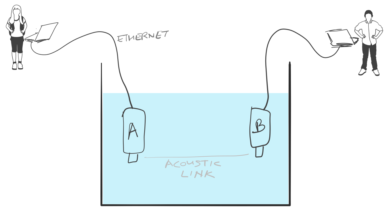
On each computer, open a web browser and key in the IP address of the respective modem. This should give us a command shell for node A and node B on the two computers.
| If you only have one computer available, you can connect both modems to the same Ethernet switch and connect to each modem’s IP address in separate browser windows. |
When working with modems, you may need to adjust the transmit power level to a suitable level for use in the water body that you have the modems in. Too high or too low a power level will not allow the modems to communicate well. The modem transmit power can be adjusted using the
plvl
command. Type
help plvl
on the command shell for node A to see examples of how the command is used:
> help plvl
plvl - get/set TX power level for all PHY channel types

Examples:
  plvl                       // get all power levels
  plvl -10                   // set all power to -10 dB
  plvl(-10)                  // alternative syntax
  plvl = -10                 // alternative syntax
The
help
command is your friend! Just type
help
to see a list of help topics. Type
help
followed by a command name, topic or parameter (you’ll learn more about these later) to get help information.
|
Assuming you have the modems in a bucket, you’ll need a fairly low transmit power. On node A, let us set the transmit power to -50 dB and try a transmission:
> plvl -50
OK
> tell 0, 'hello!'
AGREE| A poor acoustic connection between modems can lead to multiple retransmits that can take many tens of seconds before successful delivery of message, or eventual delivery failure. |
If all goes well, you should see the message on node B:
[232]: hello!Of course you’ll see a different "from" address than the one shown in the example here. It will be the actual address of your modem A. In case you don’t see the message on node B after a few seconds, you may want to adjust the power level up or down and try again.
All the other examples shown earlier in this chapter will also work with the modems. You’ll just need to replace the
localhost
with the appropriate modem IP address, and the API port for the modem will usually be 1100.
|
2.7. Transmitting and recording arbitrary acoustic waveforms
If you have UnetStack-compatible acoustic modems that support the BASEBAND service, you can use them to transmit and record arbitrary acoustic signals. Even without access to modems, you can try this out using the Unet audio SDOAM — a fully functional modem that uses your computer’s soundcard for transmission and reception. To start Unet audio, open a terminal window in the simulator’s root folder and type:
$ bin/unet audio
Modem web: http://localhost:8080/
This should start up the SDOAM and open a browser with a command shell accessing the modem. If the browser does not automatically open, just enter the modem web URL shown above in your browser. At the command shell, you can try transmitting a message:
> tell 0, 'hello!'
AGREE
You should hear the transmission from your computer speaker! If you don’t, check your speaker volume and try again.
If you have 2 computers running the Unet audio SDOAM, you can receive the transmitted signal on the second computer and see the received message:
[1]: hello!
.
|
Next, try sending a simple 10 kHz tonal signal:
> bbtx cw(10000, 0.5)                    (1)
AGREE
phy >> TxFrameNtf:INFORM[txTime:4104441] (2)| 1 | Request transmission of a continuous wave (cw) signal of 10 kHz and 0.5 seconds duration. |
| 2 | Notification that the signal was successfully transmitted. |
You should hear a 0.5 second 10 kHz tone from your computer speaker. The
bbtx
command requests transmission of a baseband signal. The function
cw()
generates such a signal based on the specified frequency and duration.
To generate the baseband representation of the signal you wish to transmit, you will need to know the carrier frequency and the baseband sampling rate of the modem:
> phy.basebandRate
12000.0
> phy.carrierFrequency
12000.0
For the Unet audio SDOAM, the carrier frequency is 12 kHz and the baseband sampling rate is 12 kSa/s.
| The baseband signal is represented as a floating point array with alternate real and imaginary components in Java/Groovy. For languages that support complex numbers (e.g. Python, Julia), the signal is simply an array of complex numbers. |
You can equally easily ask the SDOAM to make an acoustic recording for you:
> bbrec 12000                            (1)
AGREE
phy >> RxBasebandSignalNtf:INFORM[adc:1 rxTime:1911353 rssi:-61.2 fc:12000.0 fs:12000.0 (12000 baseband samples)]| 1 | Request recording of 12000 baseband samples (1 second duration). |
The recording is sent to you as a
RxBasebandSignalNtf
message with 12000 baseband samples in the
signal
field. You can check the first 32 samples:
> ntf.signal[0..31]
[-3.735939E-4, 6.7323225E-4, 7.94507E-4, 5.0331384E-4, 0.0012656008, -0.0010853912, -2.0923217E-4, -8.322359E-4, 1.5215082E-4, 2.417963E-4, -3.0220395E-5, -5.190366E-4, -6.904016E-4, -7.3395047E-4, 3.9846844E-5, 5.161132E-4, 0.0013477469, 6.2060537E-4, 1.00925405E-4, -3.974573E-4, -8.8431453E-4, -5.807383E-4, -5.730035E-4, -8.5867435E-4, -9.026667E-4, 2.2320295E-5, -1.7575005E-5, 0.0010946163, 7.7881676E-4, -3.7582265E-4, -9.449492E-4, -1.7722705E-4]
The values you’d see would natually be different, since the SDOAM would have recorded whatever sounds it heard using your computer’s microphone.
While we illustrated the use of the BASEBAND service using the
bbtx
and
bbrec
commands, the same functionality can be accessed using the
TxBasebandSignalReq
and the
RecordBasebandSignalReq
messages. This is useful if you want to access the functionality from an agent or through the external gateway API (e.g. from a Jupyter Python notebook). You will learn how to do this in
Chapter 16
.
|
3. UnetStack basics
UnetStack is an agent-based network stack . Each agent is similar to a layer in a traditional network stack, but has more flexibility to use the scarce resources (bandwidth, energy, etc) in the Unet more efficiently. In order to develop Unet applications, we need to understand some basic concepts in UnetStack.
3.1. The command shell
The simplest way to interact with UnetStack is via the command shell (or simply shell ). The shell may be accessed on the console, a TCP/IP port or via the web interface. In Chapter 2 , we have already seen how to set up a 2-node network and access the command shell for each of the nodes using a web browser. For the rest of this section, we assume that you have shells open on nodes A and B.
On node A, we can ask for a list of agents running:
> ps
statemanager: org.arl.unet.state.StateManager - IDLE
remote: org.arl.unet.remote.RemoteControl - IDLE
rdp: org.arl.unet.net.RouteDiscoveryProtocol - IDLE
ranging: org.arl.unet.localization.Ranging - IDLE
uwlink: org.arl.unet.link.ReliableLink - IDLE
node: org.arl.unet.nodeinfo.NodeInfo - IDLE
websh: org.arl.fjage.shell.ShellAgent - RUNNING
simulator: org.arl.unet.sim.SimulationAgent - IDLE
phy: org.arl.unet.sim.HalfDuplexModem - IDLE
bbmon: org.arl.unet.bb.BasebandSignalMonitor - IDLE
arp: org.arl.unet.addr.AddressResolution - IDLE
transport: org.arl.unet.transport.SWTransport - IDLE
router: org.arl.unet.net.Router - IDLE
mac: org.arl.unet.mac.CSMA - IDLE
We can further ask for more details of a specific agent:
> phy
« Half-duplex modem »

Generic half duplex modem simulator.

[org.arl.unet.DatagramParam]
  MTU ⤇ 56
  RTU ⤇ 56

[org.arl.unet.bb.BasebandParam]
  basebandRate = 12000.0
  carrierFrequency = 12000.0
  maxPreambleID ⤇ 4
  maxSignalLength = 65536
  signalPowerLevel = -42.0

[org.arl.unet.phy.PhysicalParam]
  busy ⤇ false
  maxPowerLevel = 0.0
  minPowerLevel = -96.0
  propagationSpeed ⤇ 1534.4574
  refPowerLevel = 185.0
  rxEnable = true
  rxSensitivity = -200.0
  time ⤇ 3074996380
  timestampedTxDelay = 1.0

[org.arl.unet.sim.HalfDuplexModemParam]
  basebandRxDuration = 1.0
  clockOffset = 2932.3245
We asked for details of the agent
phy
, and we got a list of parameters supported by the agent. We can get or set individual parameters of the agent:
> phy.MTU
56
> phy.rxEnable
true
> phy.rxEnable = false
false
> phy.rxEnable
false
> phy.rxEnable = true
true
To find out more about a specific parameter, we can ask for help on the parameter:
> help phy.MTU
phy.MTU - maximum transmission unit (MTU) in bytes
> help phy.rxEnable
phy.rxEnable - true if reception enabled
We can also ask for help on an agent:
> help phy
phy - access to physical service

Examples:
  phy                           // access physical parameters
  phy[CONTROL]                  // access control channel parameters
  phy[DATA]                     // access data channel parameters
  phy << msg                    // send request msg to physical agent
  phy.rxEnable = false          // disable reception of frames

Commands:

- pclr - clear PHY queues
- plvl - get/set TX power level for all PHY channel types

Parameters:

The following parameters are available on all modems. Additional modem
dependent parameters are also available. For information on these
parameters type "help modem".

- phy.MTU - maximum transmission unit (MTU) in bytes
- phy.RTU - recommended data transfer size in bytes
- phy.rxEnable - true if reception enabled
- phy.propagationSpeed - propagation speed in m/s
- phy.timestampedTxDelay - delay before TX of timestamped frames
- phy.time - physical layer time (us)
- phy.busy - true if modem is TX/RX a frame, false if idle
- phy.refPowerLevel - reference power level in dB re uPa @ 1m
- phy.maxPowerLevel - maximum supported power level (relative to reference)
- phy.minPowerLevel - minimum supported power level (relative to reference)

Channel Parameters:

The following parameters are available on all modems. Additional modem
dependent parameters are also available. For information on these
parameters type "help modem".

- phy[].MTU - maximum transmission unit (MTU) in bytes
- phy[].RTU - recommended data transfer size in bytes
- phy[].dataRate - effective frame data rate (bps)
- phy[].frameDuration - frame duration (seconds)
- phy[].powerLevel - powel level used for transmission (relative to reference)
- phy[].errorDetection - number of bytes for error detection
- phy[].frameLength - frame length (bytes)
- phy[].maxFrameLength - maximum settable frame length (bytes)
- phy[].fec - forward error correction code
- phy[].fecList - list of available forward error correction codes
From this help, we see that
phy
agent also supports channel parameters (also known as
indexed
parameters). It supports two logical channels, CONTROL (1) and DATA (2). The CONTROL channel is meant for low-rate robust data transmission, whereas the DATA channel is typically configured for higher rate data transmission. Channel parameters work in the same way as normal parameters, but with an index:
> phy[CONTROL]
« PHY »

[org.arl.unet.DatagramParam]
  MTU ⤇ 16
  RTU ⤇ 16

[org.arl.unet.phy.PhysicalChannelParam]
  dataRate = 202.10527
  errorDetection ⤇ 1
  fec ⤇ 0
  fecList ⤇ null
  frameDuration ⤇ 0.95
  frameLength = 24
  janus = false
  llr ⤇ false
  maxFrameLength = 128
  powerLevel = -42.0

> phy[DATA]
« PHY »

[org.arl.unet.DatagramParam]
  MTU ⤇ 56
  RTU ⤇ 56

[org.arl.unet.phy.PhysicalChannelParam]
  dataRate = 731.4286
  errorDetection ⤇ 1
  fec ⤇ 0
  fecList ⤇ null
  frameDuration ⤇ 0.7
  frameLength = 64
  janus = false
  llr ⤇ false
  maxFrameLength = 512
  powerLevel = -42.0

> phy[CONTROL].MTU
16
> phy[CONTROL].frameLength = 32
32
> phy[CONTROL].frameLength
32
> phy[CONTROL].MTU
24
> phy[CONTROL].frameLength = 24
24
The actual parameters you see may differ if you are working with a modem, depending on the specific capabilities of the modem. Use
help
to find out more about any listed parameter on your modem, or refer to the modem’s documentation for further information.
|
Most agents also support some commands. For example, the
phy
agent supports the
plvl
command:
> help plvl
plvl - get/set TX power level for all PHY channel types

Examples:
  plvl                       // get all power levels
  plvl -10                   // set all power to -10 dB
  plvl(-10)                  // alternative syntax
  plvl = -10                 // alternative syntax

> plvl
phy[1].powerLevel = -42.0
phy[2].powerLevel = -42.0
phy[3].powerLevel = -42.0
phy.signalPowerLevel = -42.0
> plvl -20
OK
> plvl
phy[1].powerLevel = -20.0
phy[2].powerLevel = -20.0
phy[3].powerLevel = -20.0
phy.signalPowerLevel = -20.0
The
plvl
command simply displays or sets the
powerLevel
parameter of all channels. The same can be manually accomplished by setting or getting individual parameters, if desired:
> phy[1].powerLevel
-20
> phy[1].powerLevel = -10
-10
> phy[1].powerLevel
-10
> plvl
phy[1].powerLevel = -10.0
phy[2].powerLevel = -20.0
phy[3].powerLevel = -20.0
phy.signalPowerLevel = -20.0
While
plvl
seems like a command to just set/get a
powerLevel
parameter, it does that for several channels in one go. This can save you a lot of time and typing — to achieve the same thing manually, you’d be typing 4 commands!
|
3.2. Interacting with agents using messages
While you can access a lot of functionality via parameters and commands, to fully harness the power of UnetStack, we require an understanding of the underlying messaging system between the agents. All agents support messages that expose their functionality. In fact, all parameters and commands are implemented by exchanging messages between the shell agent and other agents. In this section, we’ll take a brief look at how messaging between agents works.
All parameters and commands are implemented by exchanging messages between the shell agent and other agents. When you get/set a parameter, all the shell is doing is sending a
ParameterReq
message to the appropriate agent, and showing you the
ParameterRsp
message that the agent responds with.
|
Typically, we would want to send a
request
to an agent and get a
response
message back. This can be accomplished with the
request
call (or the equivalent alias
<<
) on the agent:
> phy << new TxFrameReq(data: [1,2,3])
AGREE
phy >> TxFrameNtf:INFORM[type:CONTROL txTime:2913909740]
Here we made a request to the
phy
agent to transmit some data. The agent responded with an
AGREE
response, shortly followed by a
TxFrameNtf
notification from
phy
telling us that the transmission was successful.
| A frame is simply a datagram at the physical layer, also sometimes called a "packet". We prefer the term "frame" when working at the physical layer, but the distinction between frames and datagrams is unimportant at this point in time. We will come back to this later, in Chapter 15 . |
We can also use the return value in a condition, but we need to remember that the return value from the
request
is a message:
> x = phy << new TxFrameReq();
phy >> TxFrameNtf:INFORM[type:CONTROL txTime:3381446740]
> x
AGREE
> x.class
class org.arl.fjage.Message
> x.performative
AGREE
> if (x.performative == Performative.AGREE) print 'OK'
OK| The semicolon ";" at the end of the first statement prevents the return value from being printed on the shell. |
Unsolicited notification messages can be received by subscribing to the topic of interest. For example, on node B, we can subscribe to physical layer events on node B:
> subscribe phy
Now, if we broadcast a frame from node A using
phy << new TxFrameReq()
, we will see the relevant reception events on node B:
phy >> RxFrameStartNtf:INFORM[type:CONTROL rxTime:1765508396]
phy >> RxFrameNtf:INFORM[type:CONTROL from:232 rxTime:1765508396]
The first event
RxFrameStartNtf
is triggered as soon as the frame is detected at node B. The second event
RxFrameNtf
is triggered when the frame is fully received, demodulated and successfully decoded at the receiver.
If all of this seems somewhat confusing to you, don’t worry about it. Most of the basic functionality of the stack can be accessed without having to deal with messages directly. As we need functionality that requires an understanding of messaging, we’ll gradually introduce them in later chapters.
3.3. Shell scripting
The default UnetStack shell accepts any Groovy code, and so is very flexible:
> 1+2
3
> 5.times { print it }
0
1
2
3
4
You can also define closures (if you’re not familiar with closures, you can think of them as functions for now):
> tx2 = {
-   2.times {
-     phy << new TxFrameReq()
-   }
- };
and call them later:
> tx2
phy >> TxFrameNtf:INFORM[type:CONTROL txTime:3911898740]
phy >> TxFrameNtf:INFORM[type:CONTROL txTime:3912307740]
You can write Groovy scripts and store them in the
scripts
folder with an extension
.groovy
. You can then invoke them from the shell by simply typing the name of the script (without the extension).
|
This only scratches the surface of what the command shell is capable of. However, it should provide you a basic understanding of how the shell works, and illustrate its power. To understand more, we suggest that you explore the online
help
. As you further understand the UnetStack and fjåge API, you’ll develop expertise on using the shell.
Part II: Setting up underwater networks
4. Unet basics
Now that we have a basic understanding of how UnetStack works, it is time to take the next step into setting up and configuring underwater networks, or simply Unets .
4.1. Node names and addresses
Unet nodes are identified by unique addresses within the Unet. Small Unets might use 8-bit addresses, supporting up to 255 different nodes. Larger Unets might use 16-bit addresses, supporting up to 65535 different nodes in the network. The address space is controlled by the parameter
node.addressSize
, and must be set to the same value (either 8 or 16) on all nodes in a Unet.
| The code examples in this chapter assume that you have a simulated Unet (the 2-node-network simulation from Chapter 2 ) running, and you’re connected to the shell of one of the nodes. However, if you have access to modems, you may choose to use the real Unet and connect to the shell of one of the modem nodes. |
To check the current address size on your node:
> node
« Node information »

Manages and maintains node information and attributes.

[org.arl.unet.nodeinfo.NodeInfoParam]
  nodeName = A
  address = 232
  addressSize = 8
  canForward = true
  mobility = false
  location = [0.0, 0.0, -15.0]
  origin = [NaN, NaN]
Some node parameters have not been shown in the above listing for brevity.
Address 0 is a broadcast address. All other addresses may be assigned to nodes in a Unet. Each Unet node is also associated with a node name (
node.nodeName
). If a node name is not explicity set, it defaults to the string representation of the node address. Descriptive node names may be used, if desired:
> node.nodeName = 'buoy_A'
buoy_A
> node
« Node information »

Manages and maintains node information and attributes.

[org.arl.unet.nodeinfo.NodeInfoParam]
  nodeName = buoy_A
  address = 232
  addressSize = 8
  canForward = true
  mobility = false
  location = [0.0, 0.0, -15.0]
  origin = [NaN, NaN]
It is recommended that, if descriptive node names are used, the corresponding node addresses be set using the ADDRESS_RESOLUTION service. This ensures that name-to-address resolution leads to the correct address for the node. The ADDRESS_RESOLUTION service can be accessed via the
host()
shell command:
> host('buoy_A')
68
> node.address = host(node.nodeName)
68
The default ADDRESS_RESOLUTION agent in the UnetStack maps node names to node addresses using a hash function. The method reduces network traffic for host name resolution, but can lead to address conflicts between nodes if two names happen to map to the same address. It is the responsibility of the network engineer to resolve address conflicts manually during the setup of the network, if the default ADDRESS_RESOLUTION agent is used. For small networks, this is simply a matter of checking that all chosen node names in the network lead to unique node addresses:
> ['buoy_A', 'auv_1', 'auv_2', 'sensor_adcp1', 'sensor_ctd1'].each { name ->
-   print "${name}: ${host(name)}"
- };
buoy_A: 68
auv_1: 150
auv_2: 109
sensor_adcp1: 43
sensor_ctd1: 14
4.2. Protocol numbers
Datagrams represent packets of data sent between nodes. Each node may have multiple agents and applications running on it, and so we need a way to specify which application the datagram is meant for. To aid with this, each datagram is associated with a protocol number that identifies the consumer on the destination node that the datagram is intended for. The consumer may be an agent or an end-user application. Protocol numbers can be thought of as port numbers in TCP/IP or UDP/IP.
The consumer may be an agent or an end-user application. Protocol number 0 (
Protocol.DATA
) is used for generic application data. Protocol numbers from 1 to
Protocol.USER-1
(31) are reserved for use by default stack agents. Protocol numbers from
Protocol.USER
(32) to
Protocol.MAX
(63) are available for end-user applications to use.
On node B, type:
> s = new UnetSocket(this);
> s.bind(Protocol.USER);                // listen for datagrams with Protocol.USER
> rx = s.receive()
to wait for a reception with
Protocol.USER
.
On node A, type:
> s = new UnetSocket(this);
> s.connect(host('B'), Protocol.DATA); // send datagrams with Protocol.DATA
> s.send('hi!' as byte[]);
> s.connect(host('B'), Protocol.USER); // send datagrams with Protocol.USER
> s.send('hello!' as byte[]);
> s.close()
Node B will receive only the second message, since it is listening for datagrams with
Protocol.USER
only. We can confirm this by checking the data in the received datagram on the command shell for node B, and close the socket:
DatagramNtf:INFORM[from:68 to:31 protocol:32 (6 bytes)]
> new String(rx.data)
hello!
> s.close()
5. Setting up small networks
5.1. Netiquette testbed
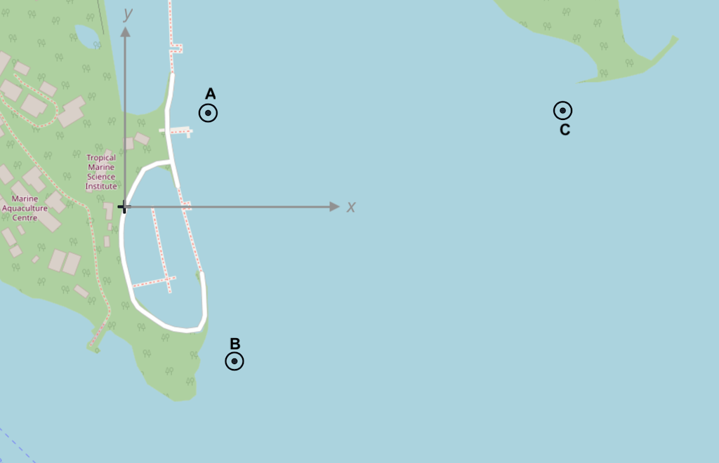
The Netiquette testbed in Singapore is a 3-node network that is deployed at sea (see Figure 4 ), and accessible over the Internet. Nodes A and B are cabled seabed mounted nodes, while node C is a solar-powered buoy. We use a simulated version of the Netiquette testbed to learn how to set up and operate small networks.
To start the simulated network, we simply run the
netq-network.groovy
simulation script:
$ bin/unet samples/netq-network.groovy

Netiquette 3-node network
-------------------------

Node A: tcp://localhost:1101, http://localhost:8081/
Node B: tcp://localhost:1102, http://localhost:8082/
Node C: tcp://localhost:1103, http://localhost:8083/
The port numbers you see in the examples above aren’t particularly special. They are simply whatever were chosen by the developer of the simulation, and can be found in the
netq-network.groovy
script. The only restriction on the choice is that placed by the OS — usually port numbers below 1024 are
reserved
and unavailable to users. Of course, they must also be unique and unused by other applications running on your computer.
|
5.2. Node names & addresses
We start off by checking the configuration of each node:
Node A
> node
« Node information »

Manages and maintains node information and attributes.

[org.arl.unet.nodeinfo.NodeInfoParam]
  address = 232
  addressSize = 8
  location = [121.0, 137.0, -10.0]
  mobility = false
  nodeName = A
  origin = [1.216, 103.851]
Node B
> node
« Node information »

Manages and maintains node information and attributes.

[org.arl.unet.nodeinfo.NodeInfoParam]
  address = 31
  addressSize = 8
  location = [160.0, -232.0, -15.0]
  mobility = false
  nodeName = B
  origin = [1.216, 103.851]
Node C
> node
« Node information »

Manages and maintains node information and attributes.

[org.arl.unet.nodeinfo.NodeInfoParam]
  address = 74
  addressSize = 8
  location = [651.0, 140.0, -5.0]
  mobility = false
  nodeName = C
  origin = [1.216, 103.851]
All nodes are configured to use 8-bit addresses. Node A has is address 232, node B is 31, and node C is 74. The origin is set to GPS location 1.216° N, 103.851° E. Locations are measured in meters relative to this origin, with
x
axis pointing east, and
y
axis pointing north. The mobility of the nodes is set to
false
to indicate that the nodes are static (for mobile nodes, mobility should be set to
true
).
In the simulated network, all of the node parameters are correctly setup by the simulator. In a real network, you may need to setup each node by manually setting the appropriate parameters. To ensure that the nodes retain the parameters between reboots, once a node is setup, simply run
savestate
on the node. This creates a
saved-state.groovy
file in the
scripts
folder with the saved settings. The settings are then automatically loaded when the node is rebooted.
|
5.3. Connectivity & ranging
Let us first check the connectivity between the nodes:
Node A
> ping host('B')
PING 31
Response from 31: seq=0 rthops=2 time=2507 ms
Response from 31: seq=1 rthops=2 time=2852 ms
Response from 31: seq=2 rthops=2 time=2852 ms
3 packets transmitted, 3 packets received, 0% packet loss
> ping host('C')
PING 74
Response from 74: seq=0 rthops=2 time=2600 ms
Response from 74: seq=1 rthops=2 time=2634 ms
Response from 74: seq=2 rthops=2 time=2737 ms
3 packets transmitted, 3 packets received, 0% packet loss
The connectivity from node A to nodes B and C looks good. What about the connectivity from node B to node C?
Node B
> ping host('C')
PING 74
Response from 74: seq=0 rthops=2 time=2810 ms
Response from 74: seq=1 rthops=2 time=2666 ms
Response from 74: seq=2 rthops=2 time=2742 ms
3 packets transmitted, 3 packets received, 0% packet loss
Looks good too!
| In this simulation, everything checks out nicely. But, in the real world, there may be packet loss to contend with. We will see how to handle those in later chapters. |
We can also check cross-check that the routes from node A to nodes B and C are direct:
Node A
> trace host('B')
[232, 31, 232]
> trace host('C')
[232, 74, 232]
The first trace shows that the datagram originated at node A (address 232), reached node B (address 31), and was sent back to node A. The second trace similarly went from node A to node C (address 74) and back. No hops in between, since our network is fully connected.
We can also make range measurements (in meters) between the nodes:
Node A
> range host('A')
0.0
> range host('B')
371.08856
> range host('C')
530.0323
Node B
> range host('A')
371.08856
> range host('B')
0.0
> range host('C')
616.0877
5.4. Sending text messages
Once we have connectivity, we can of course send text messages from the shell:
Node A
> tell host('B'), 'hello!'
AGREE
and we see the text message on node B:
Node B
[232]: hello!We have already seen in Chapter 2 and Section 4.2 on how to send text messages using the UnetSocket API from the shell, as well as from external applications. Hence we won’t dwell on it here.
5.5. File transfer and remote access
Data is often stored in files. Transferring files between nodes is a common requirement. File transfers and remote access is disabled by default. Let us enable this on node B:
Node B
> remote
« Remote control »

Text messaging and remote command execution service.

[org.arl.unet.remote.RemoteControlParam]
  cwd = unet-3.2.0/scripts
  dsp = transport
  enable = false
  groovy = true
  reliability = true
  shell = websh

> remote.enable = true
true
Now we can send & receive files, and run remote commands on node B. Let’s try it from node A:
Node A
> B = host('B')
31
> rsh B, 'tell me,"hi!"'             (1)
AGREE
[31]: hi!                            (2)
> file('abc.txt').text = 'demo';     (3)
> ls                                 (4)
abc.txt [4 bytes]
README.md [96 bytes]
> fput B, 'abc.txt'                  (5)
AGREE| 1 |
Ask node B to send a "hi!" back to me. The variable
me
is automatically defined to be the source node address during the execution of the shell command when Groovy extensions are enabled (
remote.groovy = true
).
|
| 2 | On node A, we receive a "hi!" after a short delay. |
| 3 |
Create a file
abc.txt
with
demo
as content.
|
| 4 |
List local files to check that we have a 4-byte file called
abc.txt
.
|
| 5 |
Send file
abc.txt
to node B.
|
On the shell for node B, we see the notification that the file
abc.txt
was successfully received:
Node B
remote >> RemoteFileNtf:INFORM[from:232 filename:abc.txt (4 bytes)]
Although we demonstrated file transfers between nodes with the simulator, all simulated nodes are running on your machine and so sharing the filesystem. When the file
abc.txt
was transferred from node A to B, the same file was simply overwritten, since it was created in the same folder. You could easily verify this by checking the modification time of the file on the filesystem before and after the transfer.
|
You can also use
fget
to receive a file from a remote node, but you have to remember to set
remote.enable = true
on the receiving node:
Node A
> remote.enable = true
true
> fget B, 'abc.txt'
AGREE
remote >> RemoteFileNtf:INFORM[from:31 filename:abc.txt (4 bytes)]
> fget B, 'def.txt'
AGREE
remote >> RemoteFailureNtf:INFORM[RemoteFileGetReq:REQUEST[to:31 filename:def.txt] reason:no-file]
The last command failed to get file
def.txt
, as it does not exist on node B.
When we send commands to execute on a remote node, they are usually silently executed and the output is not sent back. If we want the output to be shown to us, we need to explicity ask for it using
tell
. Since this is often required, we have a simple Groovy extensions shortcut
?
to do this for us:
Node A
> rsh B, 'tell me,node.nodeName'
AGREE
[31]: B
> rsh B, '?node.nodeName'
AGREE
[31]: B
> rsh B, '?ls'
AGREE
[31]: abc.txt [4 bytes]
README.md [759 bytes]
> rsh B, '?1+2'
AGREE
[31]: 3
> rsh B, '?"You are ${me}, I am ${node.address}"'
AGREE
[31]: You are 232, I am 31
> rsh B, '?range '+host('C')
AGREE
[31]: 616.0877
Sometimes we are not interested in the output, but simply want an acknowledgement that the command was successfully executed. For example, if we set the transmission power on a remote node, we want to know that it was set. That can be requested using the
ack
function.
Node A
> ack on
> rsh B, 'plvl -6'
AGREE
remote >> RemoteSuccessNtf:INFORM[RemoteExecReq:REQUEST[to:31 command:plvl -6 ack:true]]
> ack off
5.6. Node locations & coordinate systems
As seen in Section 5.2 , some network nodes may know their own locations. This is useful for location-based routing and other applications. Depending on the application needs, we may wish to use different coordinate systems when setting up a network. There are 4 basic options to choose from:
- No coordinates
-
We do not know or care about each node’s location.
- Local coordinates
-
We wish to work in a local coordinate system, with only relative locations of the nodes being important.
- Georeferenced local coordinates
-
We wish to work in a local coordinate system, with relative node locations specified in local coordinates. The GPS coordinate of the origin of the local coordinate system is specified.
- GPS coordinates
-
We wish to specify the GPS location of each node, without defining a local coordinate system.
When node locations are not accurately known, we can opt not to define any coordinate system. Local coordinate systems are preferred in applications where such a coordinate system can be agreed upon for the entire network. Range computation and localization is easier to do in local coordinates. GPS coordinates are used when node location is important, but a local coordinate system cannot be easily defined (e.g. ad hoc network with no prior knowledge of area of operation).
UnetStack supports all 4 options through a set of simple conventions:
- No coordinates
-
node.origin = [],node.location = []for all nodes. - Local coordinates
-
node.origin = [Float.NaN, Float.NaN]for all nodes.node.location = [x, y, z]is specified as a 3-tuple in meters. The z axis points upwards (with sealevel being considered 0 m, and the half-space underwater having negative z coordinates), but the x and y axes are arbitrarily chosen. - Georeferenced local coordinates
-
node.origin = [latitude, longitude]for all nodes, with latitude and longitude being the commonly agreed origin location.node.location = [x, y, z]is specified as a 3-tuple in meters. The x axis points east, y axis points north, and the z axis points upwards (with sealevel being considered 0 m, and the half-space underwater having negative z coordinates). - GPS coordinates
-
node.origin = []for all nodes, andnode.location = [latitude, longitude, z]where the z axis points upwards (with sealevel being considered 0 m, and the half-space underwater having negative z coordinates).
| The Unet simulator requires a local coordinate system to be defined, and so only local coordinates or georeferenced local coordinates must be used in the simulator. |
In Section 5.3 , we measured the acoustic range between nodes A and B to about about 371 m. We can check this against distance computed from the location of nodes A and B. We first get the location of node A:
Node A
> node.location
[121.0, 137.0, -10.0]
and then compute the distance to it on node B:
Node B
> distance(node.location, [121.0, 137.0, -10.0])
371.0889
We see that it agrees well with the acoustic range!
It is often necessary to convert between the GPS coordinate system and the local coordinate system. To aid in this, UnetStack provides a set of utility functions:
Node A
> gps = new org.arl.unet.utils.GpsLocalFrame(node.origin);   // set origin GPS
> gps.toGps(node.location[0..1])           // local to GPS
[1.217239, 103.852087]                     // GPS coordinates of node A
> gps.toLocal(1.21723898, 103.8520872)     // GPS to local
[120.9994, 136.9999]
> node.location
[121.0, 137.0, -10.0]
The
GpsLocalFrame
class has additional constructors and utility methods to work with GPS coordinates in degrees, minutes and seconds, if desired.
6. Routing in larger networks
6.1. MISSION 2013 network
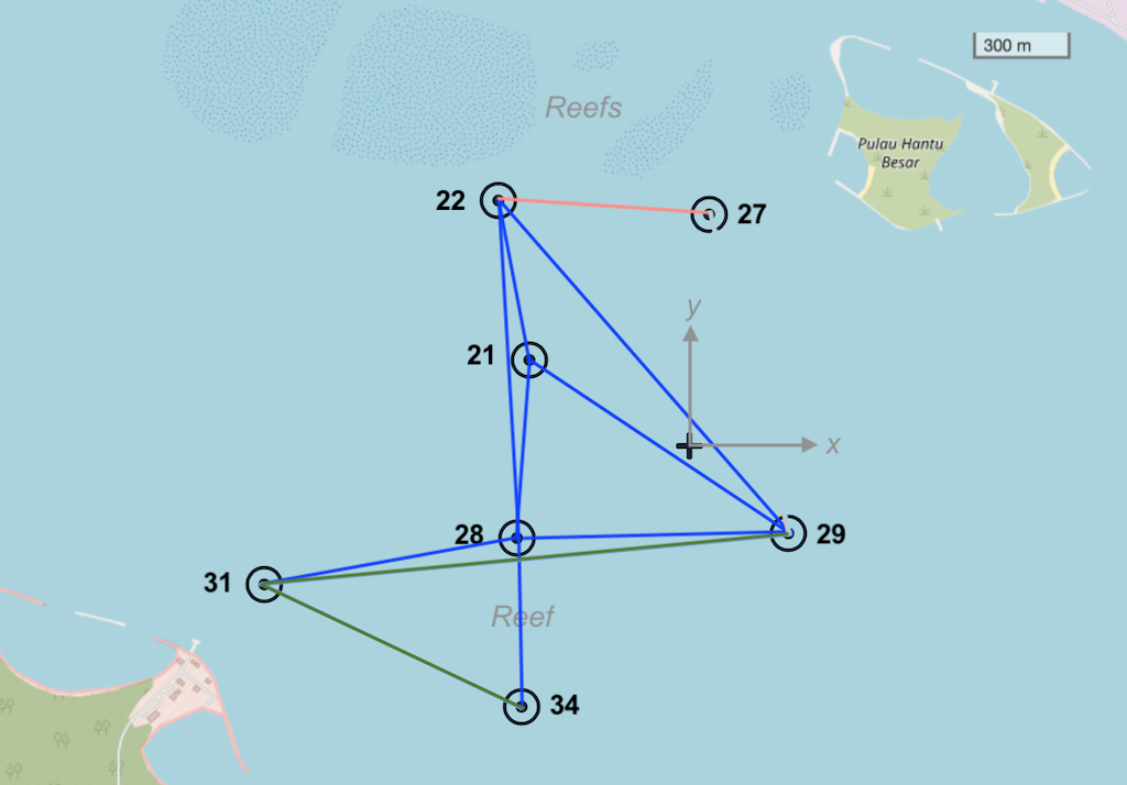
The MISSION 2013 experiment in Singapore featured a 7-node network that was deployed at sea (see
Figure 5
) for several weeks. The network operated in a challenging area with complex 3D bathymetry, several reefs and heavy shipping. During the experiment, we transmitted more than 40000 frames of data and collected statistics on communication performance across various links in the network. These performance statistics are embedded in the
Mission2013a
channel model in UnetStack. We use a simulated version of the MISSION 2013 network to learn how to set up and operate larger networks that require routing.
To start the simulated network, we simply run the
mission2013-network.groovy
simulation script:
$ bin/unet samples/mission2013-network.groovy

MISSION 2013 network
--------------------
Node 21: tcp://localhost:1121, http://localhost:8021/
Node 22: tcp://localhost:1122, http://localhost:8022/
Node 27: tcp://localhost:1127, http://localhost:8027/
Node 28: tcp://localhost:1128, http://localhost:8028/
Node 29: tcp://localhost:1129, http://localhost:8029/
Node 31: tcp://localhost:1131, http://localhost:8031/
Node 34: tcp://localhost:1134, http://localhost:8034/
While the MISSION 2013 network is not physically very large (only about 1.5 km across), the challenging environment kept the network from being fully connected, i.e., not all nodes could directly communicate with all others. The average frame delivery ratio (number of successfully delivered frames / number of transmitted frames) on each link is shown in Table 2 . The link quality is also shown on the map in Figure 5 , with dark blue links being the good ones, dark green ones being the weak ones, and brownish one being the very poor link.
| To: From: | 21 | 22 | 27 | 28 | 29 | 31 | 34 |
|---|---|---|---|---|---|---|---|
|
21 |
- |
0.926 |
0.266 |
0.917 |
0.912 |
0.000 |
0.552 |
|
22 |
0.867 |
- |
0.471 |
0.751 |
0.850 |
0.000 |
0.288 |
|
27 |
0.359 |
0.381 |
- |
0.313 |
0.322 |
0.000 |
0.000 |
|
28 |
0.847 |
0.869 |
0.390 |
- |
0.845 |
0.925 |
0.863 |
|
29 |
0.539 |
0.693 |
0.333 |
0.688 |
- |
0.374 |
0.000 |
|
31 |
0.000 |
0.000 |
0.000 |
0.902 |
0.805 |
- |
0.795 |
|
34 |
0.236 |
0.436 |
0.000 |
0.684 |
0.000 |
0.544 |
- |
6.2. Connectivity without routing
During the MISSION 2013 experiment, node 21 was a gateway node with surface expression and connectivity to the Internet (via a 3G cellular network). All other nodes were on the seabed and not directly accessible. So let us start by exploring the connectivity from node 21 to other nodes:
Node 21
> ping 22
PING 22
Response from 22: seq=0 rthops=2 time=2892 ms
Response from 22: seq=1 rthops=2 time=2912 ms
Response from 22: seq=2 rthops=2 time=3143 ms
3 packets transmitted, 3 packets received, 0% packet loss
> ping 27
PING 27
Request timeout for seq 0
Request timeout for seq 1
Response from 27: seq=2 rthops=2 time=11075 ms
3 packets transmitted, 1 packets received, 67% packet loss
> ping 28
PING 28
Response from 28: seq=0 rthops=2 time=2952 ms
Response from 28: seq=1 rthops=2 time=3110 ms
Response from 28: seq=2 rthops=2 time=3031 ms
3 packets transmitted, 3 packets received, 0% packet loss
> ping 29
PING 29
Response from 29: seq=0 rthops=2 time=3355 ms
Response from 29: seq=1 rthops=2 time=18720 ms
Request timeout for seq 2
3 packets transmitted, 2 packets received, 33% packet loss
> ping 31
PING 31
Request timeout for seq 0
Request timeout for seq 1
Request timeout for seq 2
3 packets transmitted, 0 packets received, 100% packet loss
> ping 34
PING 34
Request timeout for seq 0
Response from 34: seq=1 rthops=2 time=3294 ms
Response from 34: seq=2 rthops=2 time=3434 ms
3 packets transmitted, 2 packets received, 33% packet loss
We see that the connectivity to nodes 22 and 28 is good, that to nodes 27, 29 and 34 is poorer, and to node 31 is non-existent. Since the simulation is probabilistic, your exact results may differ.
6.3. Static routing
From Figure 5 and Table 2 , we see that node 28 has good connectivity to nodes 31 and 34, so perhaps we could relay datagrams via node 28. Although the link between 22 and 27 seems to be better than the rest, the connectivity to that node is generally poor. Let us set up the following routes:
-
Relay data between nodes 21 and 31 via node 28
-
Relay data between nodes 21 and 34 via node 28
On node 21, we add routes to nodes 31 and 34:
Node 21
> addroute 31, 28
OK
> addroute 34, 28
OK
> routes
    uuid      to nextHop         link reliability hops metric enabled
---------------------------------------------------------------------
  riddcc      31      28       uwlink        true    0    0.0    true
  fkxbqm      34      28       uwlink        true    0    0.0    true
On nodes 31 and 34, we add routes to node 21 via node 28, and enable remote access:
Node 31
> addroute 21, 28
OK
> routes
    uuid      to nextHop         link reliability hops metric enabled
---------------------------------------------------------------------
  b7m7w9      21      28       uwlink        true    0    0.0    true
> remote.enable = true
true
Node 34
> addroute 21, 28
OK
> routes
    uuid      to nextHop         link reliability hops metric enabled
---------------------------------------------------------------------
  s6pjtb      21      28       uwlink        true    0    0.0    true
> remote.enable = true
true
Now, we can check out connectivity from node 21 to nodes 31 and 34 again:
Node 21
> ping 31
PING 31
Response from 31: seq=0 rthops=4 time=18930 ms
Response from 31: seq=1 rthops=4 time=10680 ms
Response from 31: seq=2 rthops=4 time=46139 ms
3 packets transmitted, 3 packets received, 0% packet loss
> ping 34
PING 34
Response from 34: seq=0 rthops=4 time=26760 ms
Response from 34: seq=1 rthops=4 time=34408 ms
Response from 34: seq=2 rthops=4 time=21660 ms
3 packets transmitted, 3 packets received, 0% packet loss
Much better!
The pings to nodes 31 and 34 show
rthops
(round trip hops) to be 4, which makes sense, since we have 2-hop routes in each direction. We can ask the routing agent for a trace to check what route the datagram took:
Node 21
> trace 31
[21, 28, 31, 28, 21]
This shows that the datagram originated at node 21, passed through node 28 before reaching node 31. Then on the way back, it passed through node 28 again, and reached us back at node 21.
Let us next try to do something using the routes we created. We can get node 21 to ask node 31 to measure the range to node 34 and report it to us. This request will be relayed via node 28, since our routing tables are set up to do so. Remember to set
remote.enable = true
on node 31 before making the request from node 21:
Node 21
> rsh 31, '?range 34'
AGREE
[31]: 873.67
As you can see from Table 2 , the connectivity between nodes 31 and 34 is poor in this simulated network. You may need to try this command several times before you get a range estimate. When the ranging fails, you should see the message "ERROR: No response from remote node" back from node 31, which by itself demonstrates successful routing.
If you don’t have the patience to try a few times for range from node 31 to node 34, try getting a range from node 31 to 28, which will be much quicker:
rsh 31, '?range 28'
.
|
6.4. Route discovery
In the previous section, we learned how to set up static routes manually. But what if we are too lazy to determine the routes manually? Or if we don’t have access to the nodes on the seabed to set up routes? We can use the route discovery agent to populate the routing tables.
To see how to do this, let us restart our MISSION 2013 simulation so that the routing tables are empty (alternatively we can remove the routes we created earlier by typing
delroutes
on nodes 21, 31 and 34). We can verify that the routing table is indeed empty:
Node 21
> routes
No routes available
Now, start a route discovery to node 31:
Node 21
> rreq 31
OK
Patiently wait for a minute or two before checking the routing table on node 21:
Node 21
> routes
    uuid      to nextHop         link reliability hops metric enabled
---------------------------------------------------------------------
  69gnxp      22      22       uwlink        true    1    0.0    true
  ib3goj      28      28       uwlink        true    1    0.0    true
  68ozs5      29      29       uwlink        true    1    0.0    true
  gkfin2      31      29       uwlink        true    2   -1.0    true
Your routing table may differ, as the route discovery process is probabilistic. We see that we now have a route to node 31 via node 29. Let us check the routing table on node 31 as well, to see if it has a corresponding entry for a route to node 21:
Node 31
> routes
    uuid      to nextHop         link reliability hops metric enabled
---------------------------------------------------------------------
  1hveg6      28      28       uwlink        true    1    0.0    true
  pjfhin      21      28       uwlink        true    3   -1.0    true
  n5eqll      34      34       uwlink        true    1    0.0    true
  8jlzj3      21      34       uwlink        true    3   -2.0    true
   f6dit      29      29       uwlink        true    1    0.0    true
  qqtwvd      21      29       uwlink        true    3   -2.0    true
Indeed it does! In fact, it has 3 routes back to node 21, one via node 29, and two more via nodes 28 and 34. Of these routes, the route via node 28 has the largest metric, and so will be the route that is used. We can verify that by issuing a trace from node 21:
Node 21
> trace 31
[21, 29, 31, 28, 21]
Since the route discovery process is probabilistic, it may be useful to repeat the route discovery if good routes are not established after a single try. The
rreq
command can also be called with parameters to control the repetition. For example
rreq 31, 3, 6, 30
will initiate 6 route discoveries to node 31 looking for up to 3-hop routes spaced by 30 seconds between discoveries.
|
7. Wired and over-the-air links
The networks we explored in the last few chapters were completely underwater. All links were underwater acoustic links. If we wanted to replace some of the acoustic links with underwater optical or RF links, or even through-the-air cellular, WiFi or RF links, that could easily be done, as long as you had a modem driver (a specific type of agent) that supported the device that provided the link. Cellular, WiFi and other devices often already have TCP/IP network stacks running on them, to provide seamless connectivity to the Internet. UnetStack can leverage the existing network stack in these devices without having to develop new modem drivers, by translating Unet datagrams to UDP/IP datagrams, tunneling them through the IP network, and translating them back to Unet datagrams at the other end.
7.1. The UdpLink agent
The
UdpLink
agent offers the LINK service (
Chapter 21
) over an IP network.
To see how this works, let us revisit the MISSION 2013 network from Figure 5 . Recall that node 21 was a gateway node with surface expression, and was connected to the Internet via a 3G cellular IP connection. During the experiment, we had no direct acoustic connectivity between nodes 21 and 31, and hence we routed all communication to node 31 via node 28.
Let us consider a scenario where node 31 also has a surface expression and 3G cellular IP connectivity. In this case, it would be nice to have a direct link from node 21 to node 31 via UDP/IP. Let’s see how to set that up.
Fire up the
mission2013-network.groovy
network simulation (or if you already have it running from the last chapter, terminate and restart it, so that we have no routes in our routing tables). Connect to node 21’s shell and add the
UdpLink
agent, and setup a route to node 31 via the UDP link:
> container.add 'udplink', new UdpLink();
> udplink
« UDP/IP Link »

Link protocol over UDP/IP for use over wired/wireless IP networks.

[org.arl.unet.DatagramParam]
  MTU ⤇ 65535
  RTU ⤇ 1450

[org.arl.unet.link.LinkParam]
  dataRate = 0.0

[org.arl.unet.link.UdpLinkParam]
  advertise = 30
  broadcastAddress = 192.168.1.255
  monitorTimeout = 200
  port = 5100
  retries = 2
  timeout = 0.5

> addroute 31, 31, udplink
OK
> routes
    uuid      to nextHop         link reliability hops metric enabled
---------------------------------------------------------------------
  dhlx8t      31      31      udplink        true    1    0.0    true
Similarly, connect to node 31’s shell and add the
UdpLink
agent as well as a route to node 21 via the UDP link:
> container.add 'udplink', new UdpLink();
> addroute 21, 21, udplink
OK
> routes
    uuid      to nextHop         link reliability hops metric enabled
---------------------------------------------------------------------
  lbouxd      21      21      udplink        true    1    0.0    true
Go back to node 21’s shell and see if you can communicate to node 31 via the UDP link:
> ping 31
PING 31
Response from 31: seq=0 rthops=2 time=27 ms
Response from 31: seq=1 rthops=2 time=5 ms
Response from 31: seq=2 rthops=2 time=4 ms
3 packets transmitted, 3 packets received, 0% packet loss

> ack on
> tell 31, 'hello'
AGREE
remote >> RemoteSuccessNtf:INFORM[RemoteTextReq:REQUEST[to:31 text:hello ack:true]]
and on node 31, you’ll see:
[21]: helloYou’ll also notice that the communication is much faster, since the UDP/IP latency is low and data rate is much higher.
7.2. Multilink routing
When we added the
UdpLink
agent in the last section, we set up static routes manually on both nodes. Let’s delete these routes on both nodes:
> delroutesNow, let’s see what the route discovery agent does when we ask it to discover routes for us:
> rreq 31
OK
> routes      (1)
    uuid      to nextHop         link reliability hops metric enabled
---------------------------------------------------------------------
  w7iayp      31      31      udplink        true    1    0.0    true

> routes      (2)
    uuid      to nextHop         link reliability hops metric enabled
---------------------------------------------------------------------
  w7iayp      31      31      udplink        true    1    0.0    true
  6gji1z      22      22       uwlink        true    1    0.0    true
  8zhn5v      28      28       uwlink        true    1    0.0    true
  mjhfaw      31      28       uwlink        true    2   -1.0    true
  fj4g2j      34      34       uwlink        true    1    0.0    true
  2r1ymj      28      22       uwlink        true    2   -1.0    true
  ii73zj      31      22       uwlink        true    3   -2.0    true

> trace 31    (3)
[21, 31, 21]| 1 |
Checking routes within a few seconds after the
rreq
, we see that the route via the
udplink
is discovered very quickly.
|
| 2 | After a few minutes, we see that additional acoustic routes are also discovered (your routes may vary, as the route discovery is a probabilistic process). |
| 3 |
The route used for data transfer is the single-hop
udplink
route to node 31 and back.
|
Note that the route discovery resulted in 3 routes to node 31 in this case. The first one is a single-hop UDP (
udplink
) route. The second one is an acoustic route (using
uwlink
) via node 28, and the third one is a 3-hop acoustic route via node 22. We can see that the metric for the 2-hop and 3-hop acoustic routes is lower than that of the UDP route, and so the UDP route is used for data transfer. The metric is computed based on a combination of number of hops and the packet loss on a route.
You can check the routing table on node 31:
> routes
    uuid      to nextHop         link reliability hops metric enabled
---------------------------------------------------------------------
   v5lej      21      21      udplink        true    1    0.0    true
  uxl8yr      28      28       uwlink        true    1    0.0    true
  bvsu21      21      28       uwlink        true    2   -1.0    true
  9q9x91      34      34       uwlink        true    1    0.0    true
  vvzke2      21      34       uwlink        true    3   -2.0    true
We see 3 routes (direct/
udplink
, via node 28/
uwlink
and via node 34/
uwlink
), and the route with the largest metric is still the
udplink
direct route.
Part III: Building Unet applications
8. Interfacing with UnetStack
You now know how to set up a Unet. Let us next explore how you can go about interfacing your application with UnetStack to take advantage of the Unet. There are several options available:
-
The UnetSocket API ( Chapter 9 ) is the most convenient way of interface most modern applications with UnetStack. API bindings are available for many languages, including Java, Groovy, Python, Julia, Javascript and C. The API allows you to send and receive user data over the Unet, get and set agent parameters, and access advanced functionality by interacting with agents using messages.
-
UDP portals ( Section 10.1 ) provide a way to establish tunnels through the Unet for UDP datagrams. This facility can be used to transparently run applications that use UDP, over the Unet.
-
TCP portals ( Section 10.3 ) and serial portals ( Section 10.4 ) provide a way to establish connection-oriented tunnels through the Unet. This is a simple way to run applications that communicate over a TCP/IP or serial port links, over the Unet.
-
Many traditional modems provide an AT command set for applications to interact with them. While we do not encourage the use of AT commands (as they are error-prone and limited in functionality), it would be amiss not to mention that UnetStack also supports an AT script engine ( Chapter 12 ) that may be used by legacy applications to interact with it using AT commands.
9. UnetSocket API
The command shell is great for manual configuration and interaction, but often we require programmatic interaction from an external application. For this, we have the UnetSocket API (available in Java, Groovy, Python, Julia and C). While the exact syntax differs across languages, the basic concepts remain the same. We focus on the use of the API in Groovy in this section, but also show some examples in other languages.
9.1. Connecting to UnetStack
If you recall from Section 2.4 , you opened a socket connection to UnetStack on the command shell with:
> s = new UnetSocket(this);
Since the command shell was running on the node you wanted to connect to, the meaning of
this
was clear. However, in general, you’ll probably be running your application in a different process, or even on a different computer. You’ll therefore need to provide details on how to connect to the node when opening a socket.
The examples in this chapter assume that you are running:
bin/unet samples/2-node-network.groovy
|
For example, to connect to UnetStack from an application over TCP/IP, we need to know the IP address and port of the API connector on UnetStack. Simply type
iface
on the command shell of node A to find this information:
> iface
tcp://192.168.1.9:1101 [API]
ws://192.168.1.9:8081/ws [API]
websh: ws://192.168.1.9:8081/fjage/shell/ws [GroovyScriptEngine]
The first entry starting with
tcp://
is the API connector available over TCP/IP. The IP address and port number in this case are
192.168.1.9
and
1101
respectively. The IP address on your setup might differ, so remember to replace it in the example code below when you try it.
To connect to UnetStack from a Groovy application, typical code might look something like this:
import org.arl.unet.api.UnetSocket

def sock = new UnetSocket('192.168.1.9', 1101)    (1)
// do things with sock here
sock.close()| 1 |
Note that the
def
is typically not used in the shell, as we usually want the
sock
variable to be created in the shell’s context. However, we use
def
in Groovy scripts or closures to keep the
sock
variable in the local context.
|
| External applications interact with UnetStack via a UnetSocket API using fjåge’s connector framework. This allows the API to access UnetStack over a TCP/IP connection, a serial port, or any other fjåge connector that may be available. |
The code in other languages looks similar. For example, in Python:
from unetpy import UnetSocket

sock = UnetSocket('192.168.1.9', 1102)
# do things with sock here
sock.close()
A simple example application in Python using the UnetSocket API was illustrated previously in Section 2.5 .
9.2. Sending data
To send datagrams using a socket, we first specify the destination address and protocol number using the
connect()
method, and then use the
send()
method to send data (byte array). In Groovy:
def to = sock.host('B')              (1)
sock.connect(to, 0)                  (2)
sock.send('hello!' as byte[])        (3)
sock.send('more data!' as byte[])| 1 | Resolve node name to address. If the destination address is already known, this step can be skipped. |
| 2 |
Connect using protcol 0 (generic data). Constant
org.arl.unet.Protocol.DATA
may be used instead of 0 for improved readability.
|
| 3 |
Data has to be converted into a
byte[]
for transmission using the
send()
method.
|
If only a single
send()
is desired, the
connect()
call may be omitted and the destination and protocol number can be provided as parameters to
send()
:
sock.send('hello!' as byte[], to, 0)9.3. Receiving data
On the receiving end, we specify the protocol number to listen to using
bind()
, and then receive a datagram using the
receive()
method:
sock.bind(0)
def rx = sock.receive()
println(rx.from, rx.to, rx.data)
Unbound sockets listen to all unreserved protocols. So the
bind()
call above could be skipped, if we would like to listen to all application datagrams.
|
The
receive()
method above is blocking by default. The blocking behavior can be controlled using the
setTimeout()
method, where the blocking timeout can be specified in milliseconds. A timeout of 0 makes the call non-blocking. If no message is available at timeout, a
null
value is returned. When the
receive()
call is blocked, a call to
cancel()
can unblock and cause the
receive()
call to return immediately.
9.4. Getting & setting parameters
You have already been introduced to agent parameters in Chapter 3 . Applications can obtain information about an agent by reading its parameters, and can control the behavior of the agent by modifying its parameters.
To access agent parameters, you first have to look up the relevant agent based on its name or a service that it provides. For example:
def phy = sock.agentForService(org.arl.unet.Services.PHYSICAL)   (1)
println(phy.MTU)
println(phy[1].dataRate)| 1 |
Looking up an agent based on a services it provides is recommended, rather than specify the agent by name. We will explore services in more detail in
Chapter 13
. However, if you wished to reference an agent by name, you could have done that as:
def phy = sock.agent('phy')
|
This will print the value of parameter
MTU
(maximum transfer unit) of the physical layer, and the physical layer
dataRate
of the CONTROL (1) channel. You could also change some of the parameters:
println(phy[2].frameLength)
phy[2].frameLength = 32
println(phy[2].frameLength)
phy[2].frameLength = 64
Developers may wish to consider using constants
org.arl.unet.phy.Physical.CONTROL
and
org.arl.unet.phy.Physical.DATA
instead of hard coding 1 and 2, for readability.
|
The
phy
object that you received back from
sock.agentForService()
or
sock.agent()
is an
AgentID
. You can think of this as a reference to the agent. Setting and getting parameters on the agent ID sends
ParameterReq
messsages to the agent to read/modify the relevant parameters. You can also use agent IDs to send messages to the agent explicitly, as you will see next.
|
9.5. Accessing agent services
As we have already seen in Section 3.2 , the full functionality of UnetStack can be harnessed by sending/receiving messages to/from various agents in the stack. We earlier saw how to do that from the shell. We now look at how to use the UnetSocket API to send/receive messages to/from agents.
To request broadcast of a CONTROL frame, like we did before from the shell, we need to lookup the agent providing the PHYSICAL service and send a
TxFrameReq
to it:
import org.arl.unet.phy.TxFrameReq

def phy = sock.agentForService(org.arl.unet.Services.PHYSICAL)
phy << new TxFrameReq()
For lower level transactions, we obtain a fjåge Gateway instance from the UnetSocket API, and use it directly. For example, we can subscribe to event notifications from the physical layer and print them:
def gw = sock.gateway
gw.subscribe(phy)
def msg = gw.receive(10000)     (1)
if (msg) println(msg)| 1 |
Receive a message from the gateway with a timeout of 10000 ms. If no message is received during this period,
null
is returned.
|
9.6. Python and other languages
In Groovy and Java, services, parameters and messages are defined using enums and classes. These are made available to the client application by putting the relevant jars in the classpath. In other languages (e.g. Python, Julia, Javascript), services and parameters are simply referred to as strings with fully qualified names (e.g.
'org.arl.unet.Services.PHYSICAL'
). Messages are represented by dictionaries, but have to be declared before use.
For example, in Python:
from unetpy import *

sock = UnetSocket('192.168.1.9', 1102)
phy = sock.agentForService(Services.PHYSICAL)
phy << TxFrameReq()
sock.close()
If you recall from
Section 2.5
,
from
is a keyword in Python and so the
from
field in messages is replaced by
from_
. Other than this minor change, the fields in all the Python message classes are the same as the Java/Groovy versions.
|
10. Portals
Although the UnetSocket API provides great flexibility, it requires an application to explicity use the API to integrate with UnetStack. Sometimes you might have devices or applications that talk to each other over a serial cable or a UDP/IP or TCP/IP connection, and you simply want to replace the cable or connection with an underwater wireless connection. Is there an easier way for such simple Internet or serial port applications to communicate over a Unet?
The answer lies in portals. A portal is a transparent connection across the Unet. Data going in through one end of the portal travels through the Unet and emerges from the other end. The interaction with the end points of the portal is via traditional technologies such as UDP/IP sockets, TCP/IP sockets, or serial ports. This enables applications developed to use these technologies to transparently work over a Unet.
| While portals are easy to use, you should bear in mind that applications developed for the Internet or for use over serial ports do not understand the constraints and characteristics of a Unet. Some applications may use bandwidth inefficiently, or expect responses with latencies that are unreasonable for a Unet, and therefore perform poorly. |
10.1. UDP portal
Since UDP is a datagram-oriented protocol, it is easy to map UDP datagrams to Unet datagrams. This is exactly what a UDP portal does, as shown in Figure 6 .
In this example, application X sends a UDP datagram to node A, where a UdpPortal agent listens on UDP port 7000 (arbitrarily chosen port number). The UdpPortal agent converts the UDP datagram into a Unet datagram and sends it to node B. The UdpPortal agent on node B receives this datagram, converts is back to a UDP datagram and sends it to application Y listening on UDP port 7778 (also an arbitrarily chosen port number).
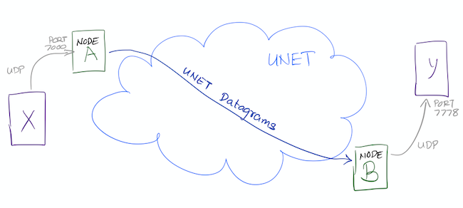
Let us emulate this example with our favorite 2-node network. Fire up the 2-node network simulation, as before:
$ bin/unet samples/2-node-network.groovy

2-node network
--------------

Node A: tcp://localhost:1101, http://localhost:8081/
Node B: tcp://localhost:1102, http://localhost:8082/
Open browser windows for shell access to each of the nodes. On node A, create a UdpPortal listening on port 7000 (since application X will send UDP datagrams to this port) and sending Unet datagrams (protocol 0 in this example, but that can be configured using the
protocol
parameter below) to node B:
> container.add 'portal', new org.arl.unet.portal.UdpPortal(port:7000, peer:host('B'));
> portal
« UDP Portal »

Transparent transport for UDP frames through a network.

[org.arl.unet.portal.UdpPortalParam]
  clientIP = 255.255.255.255
  clientPort = 7778
  dsp = uwlink
  peer = 31
  port = 7000
  priority = NORMAL
  protocol = 0
  reliability = false
The default
port
and
clientPort
for the UdpPortal are arbitrarily chosen to be 7777 and 7778 respectively. You can easily change them during creation of the UdpPortal, as we did above, or later, by setting the relevant parameter.
On node B, create the other end-point of the UDP portal to send the UDP datagrams to
localhost
UDP port 7778, where you will run application Y:
> container.add 'portal', new org.arl.unet.portal.UdpPortal(clientIP: 'localhost', clientPort: 7778);
> portal
« UDP Portal »

Transparent transport for UDP frames through a network.

[org.arl.unet.portal.UdpPortalParam]
  clientIP = localhost
  clientPort = 7778
  dsp = uwlink
  peer = 0
  port = 7777
  priority = NORMAL
  protocol = 0
  reliability = false
That’s it, your UDP portal is set up! Time to test it out!!
To test the UDP portal (and later, the TCP portal), we will use
netcat
or
nc
. If you don’t have this installed on your machine, now would be a good time to go download and install it.
|
Open a terminal window on your machine and set up a simple UDP server listening on port 7778 (application Y):
$ nc -u -l 7778
Open another terminal window and set up a simple UDP client to send text datagrams to port 7000 (application X). Assuming your IP address is
192.168.1.9
, you can do this using the command shown below. Type a text message and press ENTER.
$ nc -u 192.168.1.9 7000
hello (1)| 1 | Type your text message "hello" followed by ENTER. |
In a few seconds, you should see that text message appearing on application Y terminal:
$ nc -u -l 7778                   (1)
hello (2)| 1 | You had already typed this in earlier. |
| 2 | Your text message "hello" appears here. |
The text message went through the Unet to get there!
You may need to use the IP address of your machine (e.g.
192.168.1.9
) for the UDP connection to send the text message, rather than
localhost
. This is because the UdpPortal binds to the default network interface, and not to the loopback network interface.
|
10.2. Video streaming using UDP portal
You can do some cool things once you have set up the UDP portal. Here’s one real-life example:
Say, you wanted to stream video through the Unet. If you have
ffmpeg
installed, you can set up a UDP video client listening on port 7778:
$ ffplay udp://192.168.1.9:7778
and you can stream a video (
movie.m4v
) over UDP to port 7000:
$ ffmpeg -re -i movie.m4v -an -s cif -r 6 -c:v libx264 -b:v 15k -f mpegts udp://192.168.1.7:7000?pkt_size=512
The various flags control the quality, frame rate, and encoding of the video, and the
pkt_size
option controls the size of the datagrams sent.
The
ffmpeg
flags need to be adjusted to suit your Unet (read the
ffmpeg
documentation!). You need to ensure that the links in the Unet can support the data rates needed for this video, based on the flags you select. We have demonstrated real-time video with a high-speed acoustic underwater link with data rates of about 40 kbps.
|
10.3. TCP portal
A TCP portal is set up using the Portal agent. The Portal agent is quite similar to the UdpPortal agent, but provides more flexibility through the fjåge connectors framework. We can use a TCP connector for our TCP portal.
Restart your 2-node network, and on node A set up a TCP portal listening on port 7000:
> container.add 'portal', new org.arl.unet.portal.Portal(7000);
> portal
« Portal »

Transparent transport for TCP/IP or serial connections through a network.

[org.arl.unet.portal.PortalParam]
  delimiters = [10, 13]
  dsp = uwlink
  peer = 0
  priority = NORMAL
  protocol = 0
  reliability = false
  timeout = 1000
On node B, create the other end-point of the TCP portal listening on port 7001:
> container.add 'portal', new org.arl.unet.portal.Portal(7001);That’s it, your TCP portal is set up! Time to test it out!!
Open a terminal window on your machine and connect over TCP/IP to node A:
$ nc localhost 7000Open another terminal window and connect over TCP/IP to node B. Type a text message and press ENTER.
$ nc localhost 7001
hello (1)| 1 | Type in your text message "hello", and press ENTER. |
In a few seconds, you should see that text message appearing on the TCP/IP connection to node A:
$ nc localhost 7000               (1)
hello (2)| 1 | You had already typed this in above. |
| 2 | Your text message "hello" appears here. |
The text message went through the Unet to get there!
The TCP portal is bidirectional, so you can type something on node A, and you should see it appear on node B. The UDP portal in
Section 10.1
can also be set up as bidirectional by carefully configuring the
peer
,
port
, and
clientPort
parameters at both end-points.
|
10.4. Serial portal
Since the Portal agent uses the fjåge connectors framework, it can easily work with any type of connector. Since fjåge provides a serial port connecor, we can easily set up a serial portal on each of your nodes:
> container.add 'portal', new org.arl.unet.portal.Portal('/dev/ttyS0', 9600, 'N81');
Since many modern computers do not have serial ports, you may not be able to test the above code on your computer. If you have underwater modems with serial ports, you’ll need to replace the device name (
/dev/ttyS0
) with the appropriate serial port device name to run this code. You can also customize the serial port baud rate (
9600
) and settings (
N81
).
|
Once you have the serial portal set up on all nodes, you can connect to the node’s serial port using a serial terminal application (e.g.
minicom
) and type text messages just like you did with
nc
during the TCP portal test.
11. Wormholes
Portals ( Chapter 10 ) provide a way to transparently tunnel data through a Unet. Wormholes, on the other hand, provide a way to easily communicate between agents in different Unet nodes.
The fjåge agent framework forms the inter-agent communication backbone of a Unet node. All agents in one Unet node live in one fjåge universe , and can seamlessly communicate with each other. However, agents in different nodes live in different fjåge universes, and typically only communicate with peer agents on other nodes using protocols implemented over Unet links. Wormholes connect multiple fjåge universes over Unet links, allowing all agents in multiple nodes to transparently talk to each other!
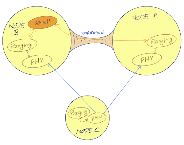
Why would we want to do this? The usefulness of this is best understood through an application that we explore next.
11.1. Diver tracking application
Imagine a network with gateway node A (a standalone buoy), surface node B (deployed from a boat), and an underwater node C (diver). Nodes A and B have underwater acoustic modems and in-air WiFi connectivity. Node C is fully submerged, and only has acoustic connectivity to nodes A and B. An diver tracking script on node B wishes to track the location of diver node C. This requires the script on node B to make range measurements btween node B and node C (easy to do!), but also between node A and node C (not so easy!). The traditional approach to this problem would be to deploy a helper agent on node A to make the range measurement, and have the script communicate with the agent using a custom protocol over a UDP link over WiFi. Another approach would be to enable remote access (
Chapter 24
) on node A, and use
rsh
to execute the ranging commands on node A, and send back the results using
tell
. While this would work, it would be quite fragile. Wormholes provide a much simpler and robust way to do this.
We’ll use the Netiquette 3-node network to demonstrate how to do this:
$ bin/unet samples/netq-network.groovy

Netiquette 3-node network
-------------------------

Node A: tcp://localhost:1101, http://localhost:8081/
Node B: tcp://localhost:1102, http://localhost:8082/
Node C: tcp://localhost:1103, http://localhost:8083/
Nodes A and B are assumed to be connected over an in-air WiFi network, and so we can enable
UdpLink
on both nodes and establish connectivity over it:
> container.add 'udplink', new UdpLink();
> addroute host('B'), host('B'), udplink
OK> container.add 'udplink', new UdpLink();
> addroute host('A'), host('A'), udplink
OK
> ping host('A')
PING 232
Response from 232: seq=0 rthops=2 time=3 ms
Response from 232: seq=1 rthops=2 time=4 ms
Response from 232: seq=2 rthops=2 time=3 ms
3 packets transmitted, 3 packets received, 0% packet loss
Next, we enable the
Wormhole
agent on both nodes, and set it up to use the
udplink
for connectivity:
> container.add 'wh', new org.arl.unet.wormhole.Wormhole();
> wh.dsp = udplink;
> wh
« Wormhole »

[org.arl.unet.wormhole.WormholeParam]
  compression = true
  dsp = udplink
  publish = []
  publishTo = 0
That’s it for the setup! We’re now ready to prototype out our application over the wormhole.
The functionality we needed was to make range measurements between nodes B and C, and nodes A and C, from a script on node B. Let’s start off measuring range to node C from node B and call it
r1
:
> ranging << new RangeReq(to: host('C'))
AGREE
ranging >> RangeNtf:INFORM[from:31 to:74 range:616.0877 offset:-1751533450 rxTime:4096892937]
> r1 = ntf.range
616.0877
In a script, you’d probably want to use
ntf = receive(RangeNtf, 5000)
to access the
RangeNtf
that comes back, but we’ll stick to doing this just in the shell for the demonstration. Now comes the
magic
. From the shell on node B, we want to ask the ranging agent on node A (address 232) to make a range measurement to node C for us:
> agent('ranging@232') << new RangeReq(to: host('C'))
AGREE
ranging@232 >> RangeNtf:INFORM[from:232 to:74 range:530.0323 offset:636287273 rxTime:1806486132]
> r2 = ntf.range
530.0323
We are able to communicate with agents on other nodes connected through the wormhole by simply adding a suffix
@999
where
999
is the node address. So
ranging@232
refers to the agent
ranging
on node with address
232
.
|
Now that we have
r1
and
r2
, we can use it to compute the location of the diver in our script.
11.2. Publishing and subscribing over wormholes
In the diver tracking application above, we performed two-way travel-time (TWTT) ranging from nodes A and B to node C. While this works well, each diver location measurement required transmission of 4 frames. With one-way travel-time (OWTT) ranging (see Chapter 17 ), we could make each measurement in just one transmission from diver node C, as long as we had accurate clocks at all nodes.
First, let us enable OWTT ranging by synchronizing clocks between nodes A and C, and nodes B and C (see Section 17.3.2 for details):
> ranging[host('C')].lifetime = 3600
3600
> range host('C')
530.0323
> ranging[host('C')].sync    // verify that the sync was achieved
true
> subscribe ranging> ranging[host('C')].lifetime = 3600
3600
> range host('C')
616.0877
> ranging[host('C')].sync // verify that the sync was achieved
true
> subscribe ranging
OWTT is now enabled. To send out a beacon on node C, we use the
beacon
command (or equivalently send a
BeaconReq
message):
> beacon
AGREE
On nodes A and B, you’ll see the
RangeNtf
notifications:
ranging >> RangeNtf:INFORM[from:232 to:74 range:530.0323 rxTime:3059430132]ranging >> RangeNtf:INFORM[from:31 to:74 range:616.0877 rxTime:5447306937]
Diver node C can now send out a beacon transmission regularly, and ranging agents on node A and node B will publish
RangeNtf
notifications on their respective agent topics. On node B, we would then want to subscribe to the ranging agent topics on both nodes. We are already subscribed to node B’s ranging agent, and connected over the wormhole (established in the previous section) to node A. Since we can refer to the ranging agent on node A as
agent('ranging@232')
, we should be able to subscribe to it:
> subscribe agent('ranging@232')
Now, try sending a
beacon
again from node C, and see what we get at node B:
ranging >> RangeNtf:INFORM[from:31 to:74 range:616.0877 rxTime:6152654937]We got the notification from node B’s agent, but nothing from node A! 😕
By default, wormholes do not publish messages on topics. However, it is easy to enable certain topics to be published. To enable this, we set the
wh.publish
parameter on node A:
> wh.publish = [topic(ranging)]
[ranging__ntf]
We can restrict the publication of the topic to only certain peer nodes, if we wish, by setting the
wh.publishTo
parameter to the address of the target node. By default, it is set to 0 (broadcast).
|
Now, try sending a
beacon
again from node C, and see what we get at node B:
ranging@232 >> RangeNtf:INFORM[from:232 to:74 range:530.0323 rxTime:4129955132]
ranging >> RangeNtf:INFORM[from:31 to:74 range:616.0877 rxTime:6517831937]
Cool! We got both ranges on node B now. 🙂
We can now write our application script to call
receive(RangeNtf)
to get the ranges, and computes the position of the diver everytime the diver node transmits a beacon.
12. AT script engine
| The UnetSocket API ( Chapter 9 ) is the recommended way to integrate applications with UnetStack. The AT script engine is only provided for legacy system support, and its use should be avoided in modern systems, as they suffer from several drawbacks (serialized interaction, error prone parsing, limited flexibility, lack of scripting support, etc.) |
The AT command interpreter provides support for legacy applications that prefer to interact with UnetStack using AT text commands. All AT commands begin on a fresh line with an
AT
prefix, and end with a new line (CR or LF). Spaces and other whitespace characters are considered significant. Lines without the
AT
command prefix are silently ignored and may be used as a comment in AT command files. All AT commands are case-insensitive, with the exception of Java class names and parameter names in the
AT~EXT
and
AT~MSG
commands.
A successful response to an AT command may span several lines of text followed by an
OK
to mark the end of the response. If the AT command is unsuccessful, an
ERROR
response is returned. The
OK
or
ERROR
response is also terminated by a new line (CR or LF).
Unsolicited notifications may be sent by the AT command interpreter to the user. Responses and notifications are atomic, and lines from each may not be interleaved in the other.
We describe the AT command set through examples below. The convention used in describing commands is that the command is in uppercase. Lowercase words denote parameters in the command, to be replaced by the user with appropriate values. Optional parts of the command are denoted by […].
12.1. Starting the AT command interpreter
The AT command interpreter is available as a script engine that can be loaded using a shell agent:
> iface ATScriptEngine, 5001Once started, you can connect to port 5001 (assuming you started the interpreter on TCP port 5001 as shown above) using a terminal window:
$ nc localhost 5001Now you can interact with the AT command interpreter.
You can also bind the AT command interpreter to a serial port, if desired. See
help iface
for details.
|
12.2. Basic AT commands
A small set of basic AT commands are honored by the interpreter:
-
AT— check if a command link is active:
AT
OK-
ATE0/ATE1— turn off/on echo:
ATE1
OK
AT
AT
OK
ATE0
ATE0
OK
AT
OK-
ATZ— shutdown/reboot -
AT/— repeat last AT command
12.3. Shell extensions
The interpreter can be customized using shell extensions:
-
AT~EXT=classname— load shell extension
Fields and methods exposed by a shell extension are made available in a shell using this command. Example:
AT~PLVL
ERROR
AT~EXT=org.arl.unet.phy.PhysicalShellExt
OK
AT~PLVL
PHY/1.POWERLEVEL=-42.0
PHY/2.POWERLEVEL=-42.0
PHY/3.POWERLEVEL=-42.0
PHY/4.POWERLEVEL=-42.0
PHY.SIGNALPOWERLEVEL=-42.0
OK
AT~PLVL=-3
OK
AT~PLVL
PHY/1.POWERLEVEL=-3.0
PHY/2.POWERLEVEL=-3.0
PHY/3.POWERLEVEL=-3.0
PHY/4.POWERLEVEL=-3.0
PHY.SIGNALPOWERLEVEL=-3.0
OK
The parameters to methods are specified as a comma-separated list after the
=
symbol in the command (e.g.
-3
in
AT~PLVL=-3
). The parameters may be numeric (
int
,
long
,
float
or
double
),
boolean
represented by
0
or
1
as
false
and
true
respectively, or double-quoted strings (e.g.
"this is a string"
).
12.4. Agent parameter access commands
Agent parameters may be listed, read and written to:
-
AT~agent[/index]?— list parameters:
AT~PHY?
PHY.SIGNALPOWERLEVEL=-10.0
PHY.RXENABLE=1
PHY.MAXPOWERLEVEL=0.0
PHY.MINPOWERLEVEL=-138.0
PHY.NOISE=-71.9
PHY.MTU=13
PHY.FULLDUPLEX=1
PHY.BUSY=0
PHY.RTC="Tue Jul 23 02:19:39 SGT 2019"
OK
AT~PHY/1?
PHY/1.FRAMELENGTH=18
PHY/1.FEC=3
PHY/1.MTU=13
PHY/1.DATARATE=52.554745
PHY/1.FRAMEDURATION=2.74
PHY/1.MODULATION="fhbfsk"
PHY/1.POWERLEVEL=-10.0
PHY/1.VALID=1
PHY/1.THRESHOLD=0.25
OK-
AT~agent[/index].parameter?— get parameter:
AT~PHY/1.FRAMELENGTH?
PHY/1.FRAMELENGTH=18
OK-
AT~agent[/index].parameter=value— set parameter:
AT~PHY/1.FRAMELENGTH=21
OK
AT~PHY/1.FRAMELENGTH?
PHY/1.FRAMELENGTH=21
OK
12.5. Sending and receiving messages
The command interpreter may make requests and receive message notification by defining the messages of interest and subscribing to appropriate topics:
-
AT~MSG:<msg>=<classname>:parameter[,parameter]…— define message format
Message formats defined using this command are available for requests and also used for notifications. If a message is not defined, notifications of that message type are silently ignored. The following command defines a message
DRQ
of class
org.arl.unet.DatagramReq
with 3 parameters:
to
,
protocol
and
data
in that order:
AT~MSG:DRQ=org.arl.unet.DatagramReq:to,protocol,data
OK
We also define other messages similarly:
AT~MSG:TXNTF=org.arl.unet.phy.TxFrameNtf:type,txTime
OK
AT~MSG:RXNTF=org.arl.unet.phy.RxFrameNtf:from,to,protocol,rxTime,data
OK-
AT~agent<msg=parameter[,parameter]…— make a request
Once we have defined the messages above, we can make a request to
PHY
to send a datagram to node 2 with protocol 0 and 3 bytes of data:
[1,2,3]
:
AT~PHY<DRQ=2,0,"010203"
OK
The notification for the datagram transmission completion will be displayed as an unsolicited notification:
~PHY>TXNTF=2,1994962099
The general notifications format as:
~agent>msg=parameter[,parameter]…
. If any of the parameters are
byte[]
or
float[]
, they are not included in the parameter list. Instead a colon (
:
) is added at the end of the line, and the data in hex follows on subsequent lines. Once the data ends, a period (
.
) is sent on a single line. If multiple parameters are arrays, the number of array parameters is given by the number of colons at the end of the line, and each array is terminated by a period, followed by the next array. An example is shown below:
~PHY>RXNTF=1,0,0,2095058353:
0102030405060708090A0B0C0D0E0F
1112131415161718191A1B1C1D1E1F
.-
AT~SUB=topic[,subtopic]— subscribe to a topic
Without subscribing to a topic, we see that the user is not notified about the reception of a frame, although the message type is already defined:
AT~PHY.FULLDUPLEX=1
OK
AT~PHY<DRQ=0,0,"010203"
OK
~PHY>TXNTF=2,2095026099
After subscribing to
PHY
, the received message is reported:
AT~SUB=PHY
OK
AT~PHY<DRQ=0,0,"010203"
OK
~PHY>TXNTF=2,2095026099
~PHY>RXNTF=1,0,0,2095058353:
010203
.
Here we see that the data from the
RXNTF
is included after the notification message as a
data block
. This is the case for all
byte[]
or
float[]
parameters. Each data block may span several lines, and is terminated by a period (
.
) on a line by itself. The number of data blocks to follow a notification is denoted by the number of colons (
:
) at the end of a notification.
-
AT~UNSUB=topic[,subtopic]— unsubscribe from a topic:
AT~UNSUB=PHY
OK
AT~PHY<DRQ=0,0,"010203"
OK
~PHY>TXNTF=2,2095026099
12.6. Managing the data buffer
While data may be directly included in a request message, sometimes it is useful to load data into a data buffer first, and then use it multiple times for requests. This is managed using the following commands:
-
AT~DATA:— load data buffer
Data is represented as a series of hexadecimal bytes, and may span many lines. Data entry is terminated by a period (
.
) on a line by itself:
AT~DATA:
010203
040506
.
OK
The above representation is convenient for
byte[]
parameters. However, the same representation is used for other data arrays, including
float[]
, where the IEEE floating point representation is used for the floating point number to be converted to a series of bytes.
An alternative data representation is useful for
float[]
, where the floating point numbers are directly specified:
AT~DATA:
1.54
0.78
5.92
2.00
.
OK
For this representation, it is necessary to have a decimal place (
.
) in each number, and each line to contain only one floating point number.
-
AT~DATA?— check size of data buffer:
AT~DATA:
010203
040506
.
OK
AT~DATA?
6 bytes
OK-
AT~CLRDATA— clear data buffer:
AT~CLRDATA
OK
AT~DATA?
EMPTY
OK
To use the data buffer, we simply use
"DATA"
instead of the hexadecimal data in a message. For example:
AT~SUB=PHY
OK
AT~DATA:
010203
040506
.
OK
AT~PHY<DRQ=0,0,"DATA"
OK
~PHY>TXNTF=2,3738882099
~PHY>RXNTF=1,0,0,3738925936:
010203040506
.
Part IV: Understanding UnetStack services
13. Services and capabilities
So far you’ve interacted with agents, checking and changing agent parameters, and sending and receiving messages. But how do you know which agents to send what messages to, and what agents support which parameters? The answer to this question lies in the concept of services .
13.1. Terminology
To fully understand services, we need to formally define a few terms, many of which you are already somewhat familiar with:
- Agent
-
An agent is logical entity that implements a specific functionality of the network. Loosely, an agent maps to a layer in a traditional network stack, but is more flexible. Each agent has its own thread of execution, and all agents can be thought of as running concurrently. An agent is normally referenced using its AgentID . You may think of an AgentID as the name of an agent, or a reference to the agent.
- Message
-
Agents interact with each other via messages. Agents can send and receive messages, and typically expose all their functionality as a set of messages that they will respond to. Messages are transmitted within the network stack on a node, and not between nodes in the network. Each message is tagged with a performative that summarizes the purpose of the message. Common performatives are
REQUEST,AGREE,REFUSE,FAILURE,NOT_UNDERSTOODandINFORM.
| It is easy to confuse messages, datagrams and frames. Messages are used by agents on a node to interact with other agents on the same node. They are never transmitted! Datagrams are logical packets of data that are exchanged between nodes. Datagrams may be fragmented and reassembled, and thus one datagram does not necessarily map to one transmission. Physical layer datagrams are called frames; they form the basic unit of data exchanged between nodes. |
- Request
-
Request messages ask an agent to perform some task. Such messages are marked with the performative
REQUEST, and it is a convention to name the message class with a suffixReq(e.g.DatagramReq,ParameterReq). - Response
-
When an agent receives a request, it must respond back to the requesting agent. Common responses are simply messages with the performative set to
AGREE,REFUSE,FAILUREorNOT_UNDERSTOOD. AnAGREEmessage confirms to the requester that the agent will perform the requested task. AREFUSEmessage tells the requester that the request cannot be performed. AFAILUREmessage, on the other hand, means that the agent should have been able to do the request under normal circumstances, but something went wrong. ANOT_UNDERSTOODresponse is generated if the agent does not know how to deal with the request. Other than these simple messages, responses may sometimes contain more information. Such messages are respresented by message classes with a suffixRsp(e.g.ParameterRsp), and may have a performative ofINFORMto indicate that they contain information in response to the request. - Notification
-
Agents sometimes generate unsolicited information. This information is encapsulated in a notification message, typically with a performative
INFORM. Notification messages may be sent to a specific agent, or on a topic. - Topic
-
A topic defines a publish-subscribe mechanism where an agent may publish some notifications, and other agents interested in those notifications may subscribe to the topic. Most agents have an unnamed topic associated with themselves, that other agents can subscribe to. For example, a link agent may subscribe to the topic of a physical layer agent to listen for incoming data frames from the physical layer.
- Parameters
-
Most UnetStack agents publish a number of parameters associated with them. Parameters are key-value pairs that provide information about the agent (read-only parameters), or allow controlling the behavior of the agent (read-write parameters). Parameters are technically accessed via
ParameterReqandParameterRspmessages, but a simpler notation (agent.parameter) is also available to get/set parameters. - Service
-
A service is a collection of messages (requests, responses and notifications) and parameters that an agent honors. Agents publish the list of services they offer, and you can find agents through the services they advertise.
- Capability
-
Services often define optional capabilities. These capabilities may be offered by some agents advertising a service, but may be omitted by others. An agent can be queried to check if it supports a specific capability using the
CapabilityReqmessage.
| If all of these terms pique your curiosity, you may wish to take a look at the fjåge documentation . fjåge is the underlying agent framework that UnetStack is built on. While we don’t assume familiarity with fjåge in this handbook, your understanding of UnetStack would certainly be quicker if you were to invest in building that familiarity. |
13.2. Finding service providers
In
Section 9.5
, we have already come across the
agentForService()
function that helps us find an agent that provides a specific service. In this section, we’ll explore this a bit more.
Fire up your trusty 2-node network and connect to node A’s shell:
> a = agentForService(org.arl.unet.Services.PHYSICAL);
> a.name
phy
We asked for an agent that provides the
org.arl.unet.Services.PHYSICAL
service, and UnetStack responded back with an agent ID of an agent that can provide you that service. The name of that agent on node A is
phy
.
But what if there were more than one agents capable of providing the same service? We can ask for the list of all agents that provide a service:
> agentsForService(org.arl.unet.Services.PHYSICAL)
[phy]
Well, there was only one agent providing the PHYSICAL service. Are there other services that multiple agents provide? Indeed, there are:
> agentsForService(org.arl.unet.Services.DATAGRAM)
[transport, router, uwlink, phy]
The DATAGRAM service is provided by several agents. If you were interested in all incoming datagrams, you’d need to subscribe to the topics of all these agents!
What would have happened if you only asked for
agentForService()
instead of
agentsForService()
for the DATAGRAM service? Try it:
> a = agentForService(org.arl.unet.Services.DATAGRAM);
> a.name
transport
Any one of the agents in the list is returned!
Ever wondered what we assigned the
a = agentForService(…)
, and then asked for
a.name
to see the name of the agent?
When you try to print an AgentID object on the shell, the shell tries to be helpful and queries the agent for all its parameters and displays them. In this case, we were only interested in the name and not all the parameters, so we asked the shell not to get the parameters by explicitly asking for just
a.name
.
|
You can also ask an agent for the list of services it provides:
> phy.services
[org.arl.unet.Services.PHYSICAL, org.arl.unet.Services.DATAGRAM, org.arl.unet.Services.BASEBAND]
or get a list of all services provided by all agents in the stack:
> services
org.arl.unet.Services.NODE_INFO: node
org.arl.unet.Services.PHYSICAL: phy
org.arl.unet.Services.REMOTE: remote
org.arl.unet.Services.TRANSPORT: transport
org.arl.unet.Services.ADDRESS_RESOLUTION: arp
org.arl.unet.Services.MAC: mac
org.arl.unet.Services.RANGING: ranging
org.arl.fjage.shell.Services.SHELL: websh
org.arl.unet.Services.DATAGRAM: transport router uwlink phy
org.arl.unet.Services.BASEBAND: phy
org.arl.unet.Services.LINK: uwlink
org.arl.unet.Services.ROUTING: router
org.arl.unet.Services.STATE_MANAGER: statemanager
org.arl.unet.Services.ROUTE_MAINTENANCE: rdp
13.3. Checking capabilities
So let’s say you looked up the list of agents that provide the DATAGRAM service:
> agentsForService(org.arl.unet.Services.DATAGRAM)
[transport, router, uwlink, phy]
If you wanted to send a datagram, how do you pick which one you’d rather use? Different agents may provide different optional capabilities. If you were specifically interested in a particular capability (e.g. reliability), you could ask the agent if it supported that:
> phy << new CapabilityReq(org.arl.unet.DatagramCapability.RELIABILITY)
DISCONFIRM
> uwlink << new CapabilityReq(org.arl.unet.DatagramCapability.RELIABILITY)
CONFIRM
Here, we asked
phy
if it can do reliable datagram delivery, and it said "no". Then we asked
uwlink
, and it confirmed that it can. If you needed reliable delivery of our datagram, you should choose the latter.
You can also ask an agent to list all its optional capabilities:
> transport << new CapabilityReq()
CapabilityListRsp:INFORM[PROGRESS,RELIABILITY,FRAGMENTATION,CANCELLATION]
The
transport
agent says it can do reliable datagram delivery, fragment & reassemble large datagrams (if necessary), report on the progress of large datagram transfers, and cancel datagram delivery half way through the process (if the user wishes to).
Another way you may choose a service provider is by checking its parameters. For example, the
MTU
parameter (defined in the DATAGRAM service) tells you what is the largest datagram the agent can deliver:
> phy.MTU
56
> uwlink.MTU
3145632
If you had a small datagram (56 bytes or less) to deliver, and you did not care about reliability, you could ask
phy
to deliver it for you. But, if your datagram was larger, even if you did not need reliability, you’d have to ask
uwlink
to deliver it for you.
The
MTU
parameter is the DATAGRAM service is actually
org.arl.unet.DatagramParam.MTU
. Since we only have one
MTU
parameter that
phy
advertises, there is no ambiguity in using
phy.MTU
. But if you wanted to explicitly ask for the parameter by its fully qualified name, you could send a
ParameterReq
for it:
phy << new ParameterReq().get(org.arl.unet.DatagramParam.MTU)
|
13.4. Service list
The following services are currently defined in UnetStack:
| Short name | Fully qualified name | Description | Read… |
|---|---|---|---|
|
DATAGRAM |
|
Send and receive datagrams |
|
|
PHYSICAL |
|
Physical layer |
|
|
BASEBAND |
|
Arbitrary waveform transmission & recording |
|
|
RANGING |
|
Ranging & synchronization |
|
|
NODE_INFO |
|
Node & network information |
|
|
ADDRESS_RESOLUTION |
|
Address allocation & resolution |
|
|
LINK |
|
Datagram transmission over a single hop |
|
|
MAC |
|
Medium access control |
|
|
ROUTING |
|
Routing of datagrams over a multihop network |
|
|
ROUTE_MAINTENANCE |
|
Discovery & maintenance of routes in a multihop network |
|
|
TRANSPORT |
|
Datagram transmission over a multihop network |
|
|
REMOTE |
|
Remote command execution, text messaging & file transfer |
|
|
STATE_MANAGER |
|
State persistence across node reboots |
|
|
SCHEDULER |
|
Sleep-wake scheduling for energy management |
|
|
SHELL |
|
Commmand execution & file management services |
You can enjoy reading more about these services in the next few chapters.
14. Datagram service
org.arl.unet.Services.DATAGRAM
Unets are all about sending datagrams between nodes!
The DATAGRAM service is, therefore, one of the fundamental services that many agents provide. However, different agents have very different capabilities in terms of what they can do with datagrams. Let’s take a look at what the service offers, and how to use it effectively.
14.1. Overview
14.1.1. Messages
Agents offering the DATAGRAM service support messages to transmit and receive datagrams:
-
DatagramReq⇒AGREE/REFUSE/FAILURE -
DatagramNtf— sent to the agent’s topic, when a datagram is received
14.1.2. Parameters
Agents offering the DATAGRAM service support the following parameter:
14.1.3. Capabilities
Agents may support several optional capabilities:
Agents capable of fragmentation may break a datagram into smaller datagrams, transmit each of them across the network, and reassemble them on the peer node.
If an agent advertises relaibility, it is able to acknowledge the successful delivery of the datagram. Reliability is enabled on a per-datagram basis by setting the
reliability
flag in the
DatagramReq
. Depending on whether the datagram could be successfully delivered or not, one of the following notifications is generated:
-
DatagramDeliveryNtf— sent to requestor -
DatagramFailureNtf— sent to requestor
Agents capable of reporting progress do so by periodically sending the following notification for long data transfers:
-
DatagramProgressNtf— sent to requestor on the transmitting node, and agent’s topic on the receiving node
If an agent supports cancellation, it honors the following request for stopping an ongoing data transfer:
-
DatagramCancelReq⇒AGREE/REFUSE/FAILURE/NOT_UNDERSTOOD(if unsupported)
Agents advertising this capability prioritize datagrams with higher
priority
indicated in the
DatagramReq
.
Agents that spool
DatagramReq
over extended periods of time usually advertise this capability. They discard
DatagramReq
that are undelivered after the time-to-live (
ttl
attribute of the
DatagramReq
) has expired.
Agents advertising this capability may apply data compression to incoming
DatagramReq
messages. If it does so, the peer agent will decompress the data before sending the
DatagramNtf
.
14.2. Examples
Fire up your 2-node network again, and open two browser windows — one connecting to node A’s shell, and the other to node B’s shell.
On node B:
> agentsForService(org.arl.unet.Services.DATAGRAM)
[transport, router, uwlink, phy]
> phy.MTU
56
> uwlink.MTU
848
> uwlink << new CapabilityReq()
CapabilityListRsp:INFORM[RELIABILITY,FRAGMENTATION]
> subscribe uwlink
We obtained a list of agents which provide the DATAGRAM service. We checked the
MTU
of the
phy
and
uwlink
agents, and found them to be 56 bytes and 848 bytes respectively. We decided to use the
uwlink
agent to communicate over a single-hop link between node A and B, and checked its capabilities. We found that it supports reliability and fragmentation. We then decided to listen to all datagrams received by node B’s
uwlink
agent by subscribing to its topic.
On node A:
> uwlink << new DatagramReq(to: 31, data: new byte[64])                               (1)
AGREE
> uwlink << new DatagramReq(to: 31, data: new byte[64], reliability: true)            (2)
AGREE
uwlink >> DatagramDeliveryNtf:INFORM[id:4dda055e-a533-401f-89c8-a01065ca5d70 to:31]   (3)
> uwlink << new DatagramReq(to: 37, data: new byte[64], reliability: true)            (4)
AGREE
uwlink >> DatagramFailureNtf:INFORM[id:bc65e643-6161-4b06-913c-3ff4f6985d36 to:37]    (5)
> uwlink << new DatagramReq(to: 0, data: new byte[64])                                (6)
AGREE
> uwlink << new DatagramReq(to: 0, data: new byte[64], reliability: true)             (7)
REFUSE: Reliability not supported for broadcast
> uwlink << new DatagramReq(to: 31, data: new byte[1024])                             (8)
REFUSE: Data length exceeds MTU| 1 | Send an unreliable datagram to node 31. |
| 2 | Send a reliable datagram to node 31. |
| 3 | Successful delivery of reliable datagram reported. |
| 4 | Send a reliable datagram to node 37. Since node 37 does not exist in this network, this should eventually fail. |
| 5 | Delivery failure reported (after trying for a few minutes). |
| 6 | Broadcast an unreliable datagram. |
| 7 | Broadcast request for reliable datagram is refused, as reliability requires a response from peer node and therefore cannot be supported on broadcast. |
| 8 | Datagram transmission request for data larger than MTU is also refused. |
If we look at the shell for node B, we should see the 3 successfully delivered datagrams:
uwlink >> DatagramNtf:INFORM[from:232 to:31 (64 bytes)]
uwlink >> DatagramNtf:INFORM[from:232 to:31 (64 bytes)]
uwlink >> DatagramNtf:INFORM[from:232 (64 bytes)]
Agent
uwlink
uses the PHYSICAL service (agent
phy
) to deliver the data. Since the
phy.MTU
is only 56 bytes, but our datagrams were 64 bytes, unbeknownst to us, the
uwlink
agent must have been fragmenting these datagrams and reassembling them on the other side!
|
14.3. Short-circuit delivery
We were able to successfully deliver datagrams from node A to node B in the examples in the previous section. We not only saw the
DatagramNtf
messages on node B, but also got
DatagramDeliveryNtf
on node A if
reliability
was enabled.
Let’s try it again, but with a small difference. On node A:
> uwlink << new DatagramReq(to: 31, data: new byte[32])
AGREE
We transmitted a smaller datagram, and node A happily accepted it for delivery. However, if we look at the shell for node B, we don’t see a
DatagramNtf
message corresponding to the datagram, even though you had already subscribed to
uwlink
! What’s going on? Let’s try it again, but this time enable reliability:
> uwlink << new DatagramReq(to: 31, data: new byte[32], reliability: true)
AGREE
uwlink >> DatagramDeliveryNtf:INFORM[id:4aaa86e5-9a56-46f8-bc1a-f6be33af03a4 to:31]
We see that the datagram was indeed delivered! And now, if we look at node B’s shell, we’ll see the delivery notification:
uwlink >> DatagramNtf:INFORM[from:232 to:31 (32 bytes)]
It seems that enabling reliability successfully delivered the datagram, but otherwise the
DatagramNtf
message did not appear on node B’s shell! You can try this many times, and the result will be the same. So it can’t be random packet loss in the network either. What’s going on?
To try and troubleshoot this, let’s subscribe to notifications from the
phy
agent to see if the data is arriving at the physical layer. On node B:
> subscribe phyOn node A, transmit the unreliable small datagram again:
> uwlink << new DatagramReq(to: 31, data: new byte[32])
AGREE
On node B, we now see a couple of notifications:
phy >> RxFrameStartNtf:INFORM[type:DATA rxTime:3956973678]
phy >> RxFrameNtf:INFORM[type:DATA from:232 to:31 rxTime:3956973678 (32 bytes)]
The first notification says that the physical layer detected the start of a data frame. The second notification is for a received frame with 32 bytes from node 232 to node 31. That’s our datagram!!! But why is it delivered by
phy
and not
uwlink
, when it was sent by
uwlink
on node A? And why is it a
RxFrameNtf
instead of a
DatagramNtf
?
Let’s solve the second mystery first. An
RxFrameNtf
is a subclass of
DatagramNtf
, so it is indeed a
DatagramNtf
message. We can easily verify this on node B:
> ntf
RxFrameNtf:INFORM[type:DATA from:232 to:31 rxTime:3956973678 (32 bytes)]
> ntf instanceof DatagramNtf
true
Variable
ntf
contains the last notification received. It is the
RxFrameNtf
, and it is indeed an instance of
DatagramNtf
. So, we indeed got the datagram on node B, and it was delivered as a
DatagramNtf
with the correct metadata.
But why was it sent on
phy
agent’s topic and not
uwlink
agent’s topic, like all other datagrams we transmitted?
This is due to an optimization known as
short-circuit delivery
(introduced in UnetStack 3), depicted in
Figure 8
. The
uwlink
agent on node A looked at the unreliable
DatagramReq
for 32 bytes and realized that it is within the
phy
agent’s capability (no reliability needed, and the datagram size is less than
phy.MTU
) to deliver this without the help of the
uwlink
agent. It delegated the task to the
phy
agent, which in turn send the datagram to its peer on node B, and therefore it was delivered to us by the
phy
agent on node B. This delegation not only reduces computation, but more importantly reduces the overhead of link headers in the frame, and therefore save valuable bandwidth in a resource-constrained underwater network.
Short-circuit delivery is not only done by
uwlink
, but by all agents supporting the DATAGRAM service. If a downstream agent is capable of delivering the datagram, the delivery is delegated automatically.
As a result of short-circuit delivery optimization, you need to subscribe to
all
DATAGRAM service providers to receive
DatagramNtf
messages, and not just the one you send the datagram via.
|
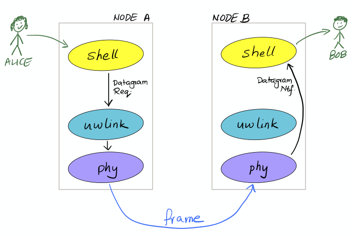
uwlink
on node A recognizes the
DatagramReq
to be within the
phy
agent’s capability, and delegates it without adding any headers. On node B, the received frame is directly delivered as a
DatagramNtf
by the
phy
agent, since
uwlink
functionality is not required.
On node B, we should have done this in the first place:
> agentsForService(org.arl.unet.Services.DATAGRAM).each { subscribe it }This single-liner in Groovy iterates over the list of agents providing the DATAGRAM service, and subscribes to the topic of each agent in that list.
Agents should use the call
subscribeForService(org.arl.unet.Services.DATAGRAM)
instead. This call subscribes to all agents providing teh DATAGRAM service, but has an added advantage: it also asks the agent to keep track of new agents that are added to the stack later, and subscribes to them if they provide the DATAGRAM service.
|
14.4. Datagrams and the UnetSocket API
The UnetSocket API also supports delivery of datagrams. Let’s try it. On node A:
> s = new UnetSocket(this);
> s.send new DatagramReq(to: 31, data: new byte[32])
true
On node B, we will see the datagram delivery:
uwlink >> DatagramNtf:INFORM[from:232 to:31 (32 bytes)]
Note that we did not have to specify an agent or service when making the datagram request via the UnetSocket API. An appropriate agent was automatically selected by the API for us. In this case, the
uwlink
agent was used by the API to deliver the datagram.
15. Physical service
org.arl.unet.Services.PHYSICAL
Agents offering the PHYSICAL service are most commonly modem drivers and modem simulators. They support messages and parameters that are explained below. PHYSICAL service providers may also provide optional capabilities to send frames triggered at a specified time, or send timestamped frames where the timestamp is embedded in the transmitted frame.
| Agents implementing the PHYSICAL service typically directly access the channel, bypassing any MAC protocol that may be in use in the network. It is highly recommended that clients wishing to use the PHYSICAL service consult with the MAC service for advice on when it is safe to access the channel, so as not to adversely affect the network performance. |
15.1. Overview
All agents supporting the PHYSICAL service must also support the DATAGRAM service ( Chapter 14 ).
15.1.1. Messages
Agents supporting the PHYSICAL service provide a set of messages to manage frame transmission and reception:
-
TxFrameReq⇒AGREE/REFUSE/FAILURE— transmit a frame -
TxRawFrameReq⇒AGREE/REFUSE/FAILURE— transmit a frame without headers -
ClearReq⇒AGREE/REFUSE/FAILURE— cancel all ongoing and pending transmissions -
RxFrameNtf— sent to agent’s topic when a frame addressed to the node is received, and the agent’sSNOOPsub-topic when a frame addressed to other nodes is overheard -
TxFrameNtf— sent to requestor when a frame is transmitted -
RxFrameStartNtf— sent to agent’s topic when a frame is detected -
TxFrameStartNtf— sent to agent’s topic when a frame transmission is started -
BadFrameNtf— sent to agent’s topic when a bad frame is received -
CollisionNtf— sent to agent’s topic when a frame is detected (and dropped) while another frame is being received
The
TxFrameReq
class extends a
DatagramReq
to add physical layer options, and the
RxFrameNtf
class extends a
DatagramNtf
to add physical layer metadata.
15.1.2. Parameters
Agents offering the PHYSICAL service support the following parameters:
-
rxEnable— true if reception is enabled, false otherwise -
propagationSpeed— signal propagation speed in m/s -
time— current physical layer clock time in microseconds -
busy— true if modem is busy transmitting/receiving (carrier sense), false if modem is idle -
refPowerLevel— reference source level in dB (re micro-Pascals @ 1m for underwater modems) -
maxPowerLevel— maximum allowable transmission power in dB rerefPowerLevel -
minPowerLevel— minimum allowable transmission power in dB rerefPowerLevel -
rxSensitivity— reference receive sensitivity (dB re micro Pascals for underwater modems)
All physical layer timestamps are in microseconds as per the clock provided by the
time
parameter. This clock is generally not synchronized with the platform clock (system time).
|
In addition to the above parameters, agents also support indexed (frame type) parameters:
-
frameDuration— frame duration in seconds (maximum duration in case of variable frame length) -
powerLevel— transmission power in dB rerefPowerLevel -
errorDetection— number of bytes used for error detection -
frameLength— frame length in bytes (maximum length in case of variable frame length) -
maxFrameLength— maximum possible frame length in bytes -
fec— forward error correction (FEC) code (0 = none/default, otherwise base 1 index from fecList) -
fecList— list of available FEC code names (in the order of increasing robustness), may be null if FEC change not supported -
dataRate— effective frame data rate (bps) -
llr— true to enable log-likelihood ratio reporting inBadFrameNtf, false otherwise
Two frame types are defined:
15.1.3. Capabilities
Agents may support several optional capabilities:
Agents advertising this capability are able to transmit frames with a transmission timestamp (start of transmission) encapsulated in the frame. This is requested through the
timestamped
flag in the
TxFrameReq
message. In order to do the timestamping, the frame has to be scheduled for transmission after a short delay. This delay is configured via an additional parameter:
-
timestampedTxDelay— delay in seconds to transmit timestamped frames
Agents advertising this capability are able to start transmitting a frame at a specified time (on a best effort basis). The time is given in the
txTime
attribute of the
TxFrameReq
message.
If an agent supports the ANEP-87 JANUS standard, it advertises this capability. An additional frame type (indexed parameter set) is defined:
-
JANUSframe = 3
The JANUS capability also adds one parameter:
-
janus— true for JANUS frame type, false for all other frame types
It also adds two JANUS-specific messages that are supported:
-
TxJanusFrameReq⇒AGREE/REFUSE/FAILURE— transmit a JANUS frame -
RxJanusFrameNtf— sent to agent’s topic when a JANUS frame is received
If an agent advertises this capability, it supports an additional request to perform FEC decoding:
-
FecDecodeReq⇒AGREE/REFUSE/FAILURE— attempt FEC decoding a frame, and if successful, send out aRxFrameNtf
15.2. CONTROL and DATA channels
The physical layer in UnetStack typically supports 2 logical channels (3 if JANUS is supported). The CONTROL channel provides low-rate, robust communication that allows exchange of small amounts of control information in the network. The DATA channel is a usually a higher rate communication link, but may require tuning to operate well in various environmental conditions.
The configurable parameters of the CONTROL and DATA channels depend strongly on the device (modem) in use. The Unet simulator provides a simplified physical layer (
HalfDuplexModem
) that captures the essential aspects of the communication using the two channels, exposing only a limited set of parameters. When configuring a real network, you should refer to your modem’s manual on advise on how best to set up the physical layer parameters.
|
Fire up the 2-node network simulation and connect to node A’s shell. If you simply type
phy
, you can explore the physical layer parameters for the node:
> phy
« Half-duplex modem »

Generic half duplex modem simulator.

[org.arl.unet.DatagramParam]
  MTU ⤇ 56
  RTU ⤇ 56

[org.arl.unet.phy.PhysicalParam]
  busy ⤇ false
  maxPowerLevel = 0.0
  minPowerLevel = -96.0
  propagationSpeed ⤇ 1534.4574
  refPowerLevel = 185.0
  rxEnable = true
  rxSensitivity = -200.0
  time ⤇ 2178921675
  timestampedTxDelay = 1.0
The
phy.MTU
and
phy.RTU
parameters tells us the maximum and recommended amount of user data that can be transmitted in a single frame (56 bytes in this case) respectively. This is based on the DATA channel, as we will see shortly, since
DatagramReq
are fulfilled using the DATA channel. The
PhysicalParam
parameters provide us information on whether the channel is busy, transmission power levels supported, receiver sensitivity, and propagation speed of the signal (e.g. speed of sound for underwater modems). The
phy.time
parameter is a microsecond resolution clock that is used to timestamp all physical layer events such as frame transmission, reception, etc.
We can dig deeper into the parameters for the CONTROL and DATA channel separately:
> phy[CONTROL]
« PHY »

[org.arl.unet.DatagramParam]
  MTU ⤇ 16
  RTU ⤇ 16

[org.arl.unet.phy.PhysicalChannelParam]
  dataRate = 202.10527
  errorDetection ⤇ 1
  fec ⤇ 0
  fecList ⤇ null
  frameDuration ⤇ 0.95
  frameLength = 24
  janus = false
  llr ⤇ false
  maxFrameLength = 128
  powerLevel = -10.0

> phy[DATA]
« PHY »

[org.arl.unet.DatagramParam]
  MTU ⤇ 56
  RTU ⤇ 56

[org.arl.unet.phy.PhysicalChannelParam]
  dataRate = 731.4286
  errorDetection ⤇ 1
  fec ⤇ 0
  fecList ⤇ null
  frameDuration ⤇ 0.7
  frameLength = 64
  janus = false
  llr ⤇ false
  maxFrameLength = 512
powerLevel = -10.0| The values you see above are specific to this simulated network, and will generally be different for different networks, depending on the devices that are being used and the environment that they are deployed in. |
Here are a few important parameters to take note of:
-
Note that
MTUfor the CONTROL channel is 16 bytes, whereas DATA channel’sMTUis 56 bytes. CONTROL frames typically carry less data, but are more robust. -
The
frameLengthfor the CONTROL and DATA channels are 8 bytes longer than the correspondingMTU. The difference is due to header information that the frames carry. The number of bytes taken by the header is device dependent, and also a function of network configuration (e.g. changes innode.addressSizemay change header size). -
Typically physical layer agents allow setting of the
frameLengthparameter, and theMTUparameter is automatically determined based on the necessary headers. ThemaxFrameLengthparameter indicates the maximum size of the frame supported. -
The
frameDurationfor the CONTROL channel is about 0.95 seconds, whereas that for the DATA channel is 0.7 seconds. While the CONTROL frames carry less data, they also have lower data rate and so may have comparable duration as the DATA frames. -
The
dataRatereported by the channel is the effective data rate in bps including the header bits, i.e., it is the frame length in bits divided by the frame duration. -
The
powerLevelparameter controls the transmission power used by the channel. This value is in dB, with reference to thephy.refPowerLevel, and may range betweenphy.minPowerLevelandphy.maxPowerLevel. -
The
errorDetectionparameter reports the number of bytes used for error detection CRC (value of 1 indicates that we are using a 8-bit CRC). Some modems will allow you to set this to 2 to switch to 16-bit CRC, if you desire a lower probability of accepting a frame with some bit errors.
15.3. Modem physical layer
In the previous section, we explored several parameters from a simplified simulated physical layer. Next let’s look at a real modem. If you are lucky enough to own one with UnetStack on it, you can connect to it’s shell now. Otherwise, we can use Unet audio SDOAM as our test modem:
$ bin/unet audio
Modem web: http://localhost:8080/
On the web shell for the modem:
> phy
« Physical layer »

Provides software-defined physical layer communication services (including error detection & correction).

[org.arl.unet.DatagramParam]
  MTU ⤇ 31
  RTU ⤇ 31

[org.arl.unet.phy.PhysicalParam]
  busy ⤇ false
  maxPowerLevel ⤇ 0.0
  minPowerLevel ⤇ -138.0
  propagationSpeed = 1500.0
  refPowerLevel ⤇ 0.0
  rxEnable = true
  rxSensitivity ⤇ 0.0
  time = 4167772
  timestampedTxDelay = 1.0

[org.arl.yoda.ModemParam]
  adcrate ⤇ 48000.0
  bbsblk ⤇ 6000
  bbscnt = 0
  bpfilter = true
  clockCalib = 1.0
  dacrate ⤇ 96000.0
  downconvRatio = 4.0
  fan = false
  fanctl = 45.0
  fullduplex = false
  gain = 0.0
  hpc = false
  inhibit = 120
  isc = true
  loopback = false
  model ⤇ Unet audio
  mute = true
  noise ⤇ -105.6
  npulses = 1
  pbsblk = 65536
  pbscnt = 0
  post = null
  poweramp = false
  preamp = true
  pulsedelay = 0
  serial ⤇ unetaudio
  standby = 15
  upconvRatio ⤇ 8.0
  vendor ⤇ UnetStack
  voltage ⤇ 0.0
  wakeupdelay = 400
  wakeuplen = 8000
For brevity, we have omitted the baseband service and scheduler service parameters in the listing above. Even then, there are many parameters that allow you to configure the SDOAM. We cannot cover each parameter in detail here, but we encourage you to explore the help pages for the parameters by simply typing
help phy.
followed by the parameter name.
Further, let’s look at the indexed parameters for the CONTROL channel:
> phy[CONTROL]
« PHY »

[org.arl.unet.DatagramParam]
  MTU ⤇ 13
  RTU ⤇ 13

[org.arl.unet.phy.PhysicalChannelParam]
  dataRate ⤇ 70.588234
  errorDetection ⤇ true
  fec = 1
  fecList ⤇ [ICONV2]
  frameDuration ⤇ 2.04
  frameLength = 18
  janus = false
  llr = false
  maxFrameLength ⤇ 796
  powerLevel = -42.0

[org.arl.yoda.FhbfskParam]
  chiplen = 1
  fmin = 9520.0
  fstep = 160.0
  hops = 13
  scrambler = 0
  sync = true
  tukey = true

[org.arl.yoda.ModemChannelParam]
  basebandExtra = 0
  basebandRx = false
  modulation = fhbfsk
  preamble = (480 samples)
  test = false
  threshold = 0.25
  valid ⤇ true
Again, we cannot cover all the parameters in detail here, but will draw your attention to a few important ones. You see that the
modulation
for the CONTROL channel is set to
'fhbfsk'
(frequency-hopping binary frequency shift keying). Depending on your modem, different modulations may be supported. Once a modulation scheme is chosen, you see additional modulation-dependent parameters. In this case, these are the
org.arl.yoda.FhbfskParam
parameters such as
fmin
,
fstep
,
hops
,
chiplen
,
tukey
, etc. These parameters allow you to control the modulation’s frequency band, number of hops, chip duration, windowing, etc.
If you change modulation parameters, you have to remember to do it on all your modems in the network. Otherwise they will be speaking different
languages
, and they won’t be able to understand each other. Not all combination of modulation parameters are valid. The
valid
parameter tells us if the current setting is valid or not. If the setting is invalid, all transmission requests will be refused.
|
The
preamble
parameter determines a detection preamble that is transmitted before each frame. This is used by the receiving modem to determine the start of a frame. The
threshold
parameter controls the detection probability and false alarm rate for frame detection. A lower threshold will improve detection probability, but increase false alarm rate.
If the
test
flag is set on the transmission and reception modems, each transmit frame is filled with known test data. This allows the receiving modem to compute the bit error rate (BER), even when the frame has too many errors for FEC to be able to correct.
15.4. Transmitting & receiving using Unet audio
If you have two computers with speakers and microphones, you could run Unet audio on both, and communicate between the two. If you happen to have only one computer handy, do not worry — we can get one Unet audio instance to transmit and receive at the same time. This is full-duplex communication!
| Real modems typically cannot do full-duplex communication because the weak incoming signals are masked by clutter from the strong outgoing signal. However, by adjusting the volume of your computer carefully, you can easily do full-duplex communication on your Unet audio SDOAM. |
On Unet audio shell, enable full-duplex operation and try a transmission (you should be able to hear it from your computer speaker!). Your output might not look exactly the same, but let’s go over all the notifications we got and see if we can understand all of them:
> phy.fullduplex = true
true
> subscribe phy
> phy << new TxFrameReq()
AGREE
phy >> TxFrameStartNtf:INFORM[type:CONTROL txTime:79322682]                (1)
phy >> RxFrameStartNtf:INFORM[type:CONTROL rxTime:79309353 detector:0.87]  (2)
phy >> RxFrameStartNtf:INFORM[type:DATA rxTime:80659519 detector:0.26]     (3)
phy >> TxFrameNtf:INFORM[type:CONTROL txTime:79310432]                     (4)
phy >> RxFrameNtf:INFORM[type:CONTROL from:1 rxTime:79309353 rssi:-29.3]   (5)
phy >> BadFrameNtf:INFORM[type:DATA rxTime:80659519 rssi:-38.5 (18 bytes)] (6)| 1 | Transmission of our requested CONTROL frame has started. |
| 2 | Our frame being transmitted was detected as a CONTROL frame, and reception has started. |
| 3 | Our frame being transmitted was wrongly detected (false alarm) as a DATA frame. |
| 4 | Transmission of our frame was completed. |
| 5 | Reception of the frame was completed, and successful. |
| 6 | The wrongly detected frame resulted in data that did not satisfy CRC, and hence reported as a bad frame. |
To get rid of the false alarm on the DATA channel, we could either increase the detection threshold or turn off the detector completely (
phy[DATA].threshold = 0
). For now, we’ll do the latter. Let’s also turn on the
phy[CONTROL].test
flag so that we can measure communication performance in terms of BER. To measure BER before error correction, we also need to turn off
phy[CONTROL].fec
:
> phy[DATA].threshold = 0
0
> phy[CONTROL].test = true
true
> phy[CONTROL].fec = 0
0
Now we can make 10 transmissions, 2 seconds apart, and watch the BER of the received frames:
> 10.times { phy << new TxFrameReq(); delay(2000); }
phy >> TxFrameNtf:INFORM[type:CONTROL txTime:204359766]
phy >> RxFrameNtf:INFORM[type:CONTROL rxTime:204385187 rssi:-28.9 cfo:0.0 ber:0/144 (18 bytes)]
phy >> TxFrameNtf:INFORM[type:CONTROL txTime:205578432]
phy >> RxFrameNtf:INFORM[type:CONTROL rxTime:205603853 rssi:-28.4 cfo:0.0 ber:0/144 (18 bytes)]
phy >> TxFrameNtf:INFORM[type:CONTROL txTime:207567766]
phy >> RxFrameNtf:INFORM[type:CONTROL rxTime:207589186 rssi:-28.5 cfo:0.0 ber:0/144 (18 bytes)]
phy >> TxFrameNtf:INFORM[type:CONTROL txTime:209583766]
phy >> RxFrameNtf:INFORM[type:CONTROL rxTime:209609187 rssi:-28.2 cfo:0.0 ber:0/144 (18 bytes)]
phy >> TxFrameNtf:INFORM[type:CONTROL txTime:211573099]
phy >> RxFrameNtf:INFORM[type:CONTROL rxTime:211594519 rssi:-28.3 cfo:0.0 ber:0/144 (18 bytes)]
phy >> TxFrameNtf:INFORM[type:CONTROL txTime:213589099]
phy >> RxFrameNtf:INFORM[type:CONTROL rxTime:213614520 rssi:-28.1 cfo:0.0 ber:0/144 (18 bytes)]
phy >> TxFrameNtf:INFORM[type:CONTROL txTime:215578432]
phy >> RxFrameNtf:INFORM[type:CONTROL rxTime:215599853 rssi:-28.5 cfo:0.0 ber:0/144 (18 bytes)]
phy >> TxFrameNtf:INFORM[type:CONTROL txTime:217594432]
phy >> RxFrameNtf:INFORM[type:CONTROL rxTime:217619853 rssi:-28.2 cfo:0.0 ber:0/144 (18 bytes)]
phy >> TxFrameNtf:INFORM[type:CONTROL txTime:219583766]
phy >> RxFrameNtf:INFORM[type:CONTROL rxTime:219605186 rssi:-28.0 cfo:0.0 ber:0/144 (18 bytes)]
phy >> TxFrameNtf:INFORM[type:CONTROL txTime:221599766]
phy >> RxFrameNtf:INFORM[type:CONTROL rxTime:221625187 rssi:-27.7 cfo:0.0 ber:0/144 (18 bytes)]
For brevity, we have omitted the
TxFrameStartNtf
and
RxFrameStartNtf
messages. We see that no bits were in error, out of 144 transmitted bits. We had perfect communication, even without FEC! This is not surprising since the speaker and microphone are very close (and hence good signal-to-noise ratio), but real channels are rarely so forgiving. You can try this between 2 computers, and things may not be as rosy.
Feel free to play around with the parameters of the modulation scheme and try transmissions to get a feel for how the parameters affect communication performance. Since your transmission and reception modems are the same, you only need to set the parameters once! In real life, you’ll need to set the same parameters on all modems in your network.
Remember to turn off the
phy[CONTROL].test
flag before trying any data transfer. While the flag is on, no user data can be carried by the transmitted frames.
|
15.5. Timed and timestamped transmissions
To explore timed and timestamped transmissions, let’s go back to our 2-node network simulation. On the shell for node A:
> phy << new CapabilityReq()
CapabilityListRsp:INFORM[TIMESTAMPED_TX,TIMED_BBREC,TIMED_BBTX,TIMED_TX]
We see that the
phy
agent supports the
TIMESTAMPED_TX
and
TIMED_TX
optional capabilities. Let us try them out. On node B:
> subscribe phyGoing back to node A, send a timestamped frame:
> phy << new TxFrameReq(timestamped: true)
AGREE
phy >> TxFrameNtf:INFORM[type:CONTROL txTime:2489196375]
We see that the frame was transmitted at time 2489196375 (when you try this, the time will of course be different). You should see the
RxFrameNtf
for this frame on node B:
phy >> RxFrameStartNtf:INFORM[type:CONTROL rxTime:687419054]
phy >> RxFrameNtf:INFORM[type:CONTROL from:232 rxTime:687419054 txTime:2489196375]
Note that the
RxFrameNtf
now has an additional
txTime
field that’s populated, and the timestamp in there is the same as the
txTime
on node A’s
TxFrameNtf
. The frame was timestamped before transmission, and transmitted at exactly the intended time.
Timestamps take up bits in the transmitted frame. Your effective
MTU
for frames with timestamps is 6 bytes less than the advertised
MTU
.
|
Do bear in mind that the
phy.time
clocks on node A and B may not be synchronized. So timestamps from one node cannot be directly compared with timestamps on another node. In the above example, the
rxTime
was 687,419,054 microseconds, whereas the
txTime
was 2,489,196,375 microseconds. This does not mean that the frame was received before it was transmitted! It’s just that node A and B have an offset between their clocks.
|
Sometimes you may not need to transmit a timestamped frame, but you do want the frame to be transmitted at a specified time. On node A:
> t = phy.time + 5000000; println(t); phy << new TxFrameReq(txTime: t) (1)
3174864375                                                             (2)
AGREE
phy >> TxFrameNtf:INFORM[type:CONTROL txTime:3174864375] (3)| 1 |
t
is the current time + 5 seconds. We ask for a frame to be transmitted at time
t
.
|
| 2 |
The value of time
t
is printed immediately (due to the
println(t)
).
|
| 3 |
The
TxFrameNtf
message will appear after a few seconds, once the transmission is made. Note that the actual
txTime
when the transmission occurred matches with our requested value
t
.
|
If you check node B’s shell, you’ll find the corresponding
RxFrameNtf
, but it will not have a
txTime
field, as the frame transmitted was not timestamped.
| The transmission time is honored on a best effort basis, which means that there could be a small difference between the requested time and the actual transmit time. |
15.6. Snooping frames meant for other nodes
If you’re familiar with Ethernet network interface cards, you may have come across promiscuous mode . In this mode, the network card receives all packets that it hears, not just the ones that are addressed to the node. Agents providing the PHYSICAL service essentially do this continuously, but they send the notifications for frames intended for other nodes on a special sub-topic called SNOOP.
With the 2-node network simulation, let’s first only subscribe to the
phy
agent’s topic on node B:
> subscribe phyFrom node A, transmit a frame to node B and to node C (node C does not exist in this network):
> phy << new TxFrameReq(to: host('B'))
AGREE
phy >> TxFrameNtf:INFORM[type:CONTROL txTime:4622534375]
> phy << new TxFrameReq(to: host('C'))
AGREE
phy >> TxFrameNtf:INFORM[type:CONTROL txTime:4623823375]
On node B, you’ll find that it receives the
RxFrameStartNtf
for both transmissions, but only the
RxFrameNtf
for the transmission addressed to node B:
phy >> RxFrameStartNtf:INFORM[type:CONTROL rxTime:2820757054]
phy >> RxFrameNtf:INFORM[type:CONTROL from:232 to:31 rxTime:2820757054]
phy >> RxFrameStartNtf:INFORM[type:CONTROL rxTime:2822046054]
The
RxFrameStartNtf
is sent when a frame is detected. At that point in time, the agent has no idea whom the frame is intended for, because the frame contents have not yet arrived. Only when the frame is received and decoded does the agent know the destination address. Seeing that the second frame was intended for node C, node B does not report a
RxFrameNtf
for it.
If you were interested in snooping conversations between other nodes, you could subscribe to the SNOOP topic on node B:
> subscribe topic(phy, org.arl.unet.phy.Physical.SNOOP)Now try transmitting another frame from node A to node C. On node A:
> phy << new TxFrameReq(to: host('C'))
AGREE
phy >> TxFrameNtf:INFORM[type:CONTROL txTime:4899843375]
Now you’ll see on node B that the corresponding
RxFrameNtf
is received:
phy >> RxFrameStartNtf:INFORM[type:CONTROL rxTime:3098066054]
phy >> RxFrameNtf:INFORM[type:CONTROL from:232 to:74 rxTime:3098066054]
The
to
address of 74 corresponds to
host('C')
, but the frame is available for agents on node B through the SNOOP topic.
16. Baseband service
org.arl.unet.Services.BASEBAND
Software-defined modems often allow developers to transmit and record arbitrary waveforms. This functionality is encapsulated in the baseband service of UnetStack.
| Agents implementing the baseband service typically directly access the channel, bypassing any MAC protocol that may be in use in the network. It is highly recommended that clients wishing to use the baseband service for transmitting arbitrary waveforms consult with the MAC service for advice on when it is safe to access the channel, so as not to adversely affect the network performance. |
16.1. Overview
Agents offering the baseband service are most commonly modem drivers (and simulators). They support a set of messages and parameters that are explained below. Baseband service providers may also provide optional capabilities to send or record signals at a specified time, or based on premable detection.
16.1.1. Messages
Agents supporting the baseband service provide messages for arbitrary signal transmission and recording:
-
TxBasebandSignalReq⇒AGREE/REFUSE/FAILURE— transmit a signal -
RecordBasebandSignalReq⇒AGREE/REFUSE/FAILURE— record a signal -
GetPreambleSignalReq⇒REFUSE/BasebandSignal— get baseband preamble signal -
RxBasebandSignalNtf— signal recording sent to requestor, or to agent’s topic if the recording was not specifically requested
During signal transmission, an agent implementing the baseband service sends out
TxFrameStartNtf
and
TxFrameNtf
, as described in the PHYSICAL service (
Chapter 15
). Similarly, if recording is triggered on a preamble detection, the agent sends out a
RxFrameStartNtf
as described in the PHYSICAL service.
Detection preambles are often added to transmitted signals for the receiving modem to identify the incoming signals. The receiving modem can capture the signal when it detects the preamble, and then send a
RxBasebandSignalNtf
. If a modem supports multiple preambles, the
TxBasebandSignalReq
can specify the
preamble
to be used. Setting the
preamble
to 0 results in a signal transmission without a preamble. Such a transmission will ordinarily not be received by any modem, unless it is recorded by an explicit
RecordBasebandSignalReq
at the appropriate time.
16.1.2. Parameters
Agents offering the baseband service support the following parameter:
-
carrierFrequency— default carrier frequency for baseband signals (Hz) -
basebandRate— default baseband sampling rate for baseband signals (samples/s) -
maxPreambleID— maximum preamble identifier supported -
maxSignalLength— maximum baseband signal length (in samples) for transmission/reception -
signalPowerLevel— signal transmission power level in dB rerefPowerLevel(refPowerLevelis specified in the PHYSICAL service)
16.1.3. Capabilities
Agents may support several optional capabilities:
Agents advertising this capability are able to transmit signals at specified time (on a best effort basis). The time is given in the
txTime
attribute of the
TxBasebandSignalReq
message.
Agents advertising this capability are able to record signals at specified time (on a best effort basis). The time is given in the
recTime
attribute of the
RecordBasebandSignalReq
message.
16.2. Baseband and passband signals
Communication systems usually represent signals in a complex baseband representation, as this allows them to be sampled at a lower sampling rate than real passband signals. Passband signals have to be sampled at more than twice the highest frequency (Nyquist criterion). Baseband signals need to be sampled at more than twice the bandwidth. Since the bandwidth is typically much lesser than the carrier frequency, the baseband representation is usually more economical than the passband representation.
While the baseband service is aimed at signals represented in the complex baseband representation, it also supports signals represented as real passband samples. Such signals are identified by setting the
fc
(carrier frequency) field of the
TxBasebandSignalReq
or
RxBasebandSignalNtf
to 0. Modems offering the baseband service may optionally support passband signal transmission and recording.
Since Java and Groovy do not support complex numbers natively, the complex baseband signals are represented by an array of floats with alternate samples from the in-phase (real part) and quadrature (imaginary part) channels. In languages that support complex numbers (e.g. Python and Julia), the signals are represented as arrays (or lists) of complex numbers.
If all this seems to be confusing, don’t worry, it’ll become clear as we go through examples shortly.
16.3. Transmitting and recording arbitrary signals
In
Section 2.7
, you already saw how to transmit and record arbitrary signals. We then used the convenience functions
bbtx
and
bbrec
for simplicity. In this chapter, we will do the same thing by sending the
TxBasebandSignalReq
and
RecordBasebandSignalReq
messages instead. As you’ll see, these messages provide you greater control, and can also be sent via the UnetSocket API or a fjåge gateway from external applications.
Fire up Unet audio to try out the examples here:
$ bin/unet audio
Modem web: http://localhost:8080/
On the shell for the Unet audio SDOAM, check which agents provide the baseband service:
> agentsForService(org.arl.unet.Services.BASEBAND)
[phy]
We can now direct all our requests to the
phy
agent. Let’s check the baseband parameters of the
phy
agent (we omit other parameters here for brevity):
> phy
« Physical layer »

Provides software-defined physical layer communication services (including error detection & correction).

[org.arl.unet.bb.BasebandParam]
  basebandRate ⤇ 12000.0
  carrierFrequency = 12000.0
  maxPreambleID ⤇ 4
  maxSignalLength ⤇ 2147483647
  signalPowerLevel = -42.0
We see that the Unet audio SDOAM operates at a carrier frequency of 12 kHz and a bandband sampling rate of 12 kSa/s. Let’s create a DC signal of length 12000 complex baseband samples (24000 floats) and transmit it. A DC signal of length 12000 complex samples with a carrier frequency of 12 kHz is a sinusoidal 12 kHz signal for 1 second.
> s = [1,0]*12000                 (1)
[1, 0, 1, 0, 1, 0, 1, 0, 1, 0, 1 <<snip>> 0, 1, 0, 1, 0, 1, 0, 1, 0, 1, 0]
> s.size()
24000
> phy << new TxBasebandSignalReq(signal: s)
AGREE
phy >> TxFrameNtf:INFORM[txTime:11401231]| 1 | In Groovy, we can repeat a list using the "*" operator. The list [1,0] represents a complex number 1+0j. Repeating it 12000 times gets us a 1 second long DC signal. |
You should hear the sound from your computer speaker.
You can generate other frequency signals using the
cw()
(continuous wave) function available in the shell. You can also save and load signals from text files using the
save
and
load
commands. For information on all these commands/functions, simply type
help cw
,
help save
or
help load
.
|
Unet audio supports transmission of passband signals as well. Let us create a half second 2000 kHz passband signal and transmit it:
> s = cw(2000, 0.5, 0)                             (1)
> s.size()
48000                                              (2)
> phy << new TxBasebandSignalReq(signal: s, fc: 0) (3)
AGREE
phy >> TxFrameNtf:INFORM[txTime:414013271]| 1 |
The
cw()
function enables us to create baseband or passband continuous wave signals. The third parameter is the carrier frequency. Setting that to 0 creates a baseband signal.
|
| 2 | Notice that our signal is 48000 floats for 0.5 seconds. Compare that with the previous DC signal, which was 24000 floats for 1 second. |
| 3 |
The
fc
field is set to 0 to tell
phy
that the
signal
is given in passband.
|
Next, let’s request a recording of 12000 samples (1 second duration):
> phy << new RecordBasebandSignalReq(recLength: 12000)
AGREE
phy >> RxBasebandSignalNtf:INFORM[adc:1 rxTime:11780353 rssi:-79.1 fc:12000.0 fs:12000.0 (12000 baseband samples)]
> ntf.signal                      (1)
[8.611694E-5, 5.8899976E-5, 1.01 <<snip>> E-6, -9.148392E-6, 3.5340495E-6]| 1 |
The
ntf
variable holds the last received notification, which in this case is the
RxBasebandSignalNtf
. The
signal
field contains the complex baseband recording.
|
You can also ask for recordings to begin at a specified time:
> t = phy.time + 5000000; println(t); phy << new RecordBasebandSignalReq(recLength: 12000, recTime: t)
855949105
AGREE
phy >> RxBasebandSignalNtf:INFORM[adc:1 rxTime:855949105 rssi:-90.3 fc:12000.0 fs:12000.0 (12000 baseband samples)]
You’d have noticed the 6 second delay (5 seconds to begin recording, 1 more second to finish the recording) before the recording notification.
Interestingly, you can also request recordings in the past! Many modems have a short buffer, allowing recording in the recent past. Go too far in the past and the modem will refuse your request!
> t = phy.time - 5000000; println(t); phy << new RecordBasebandSignalReq(recLength: 12000, recTime: t)
1186471772
AGREE
phy >> RxBasebandSignalNtf:INFORM[adc:1 rxTime:1186471772 rssi:-74.6 fc:12000.0 fs:12000.0 (12000 baseband samples)]
> t = phy.time - 60000000; println(t); phy << new RecordBasebandSignalReq(recLength: 12000, recTime: t)
1204946438
REFUSE: Bad start time
Specifying a negative
recTime
is understood by the baseband service provider as a relative time. So we can simpify our request to record 5 seconds in the past:
> phy << new RecordBasebandSignalReq(recLength: 12000, recTime: -5000000)
AGREE
phy >> RxBasebandSignalNtf:INFORM[adc:1 rxTime:1361359020 rssi:-72.9 fc:12000.0 fs:12000.0 (12000 baseband samples)]
16.4. Transmitting and detecting preambles
Each logical channel (CONTROL, DATA, etc.) is associated with a detection preamble. Detectors in a modem monitor incoming signals, and trigger when the preamble is detected.
We can transmit a preamble easily:
> phy << new TxBasebandSignalReq(preamble: 1)
AGREE
phy >> TxFrameNtf:INFORM[txTime:5470777099]
Here, we did not specify a signal to transmit, so only the preamble was transmitted. You should have heard the preamble as a short chirp from your computer speaker. If we had specified a signal, the preamble would have been followed by the signal.
If you had another Unet audio SDOAM running nearby, it would have heard the preamble and detected a CONTROL frame. It would have tried to decode the frame, but failed, as we didn’t actually transmit anything after the preamble. So you’d have seen a
RxFrameStartNtf
followed by a
BadFrameNtf
if you had subscribed to
phy
topic on that modem.
If you don’t have access to another computer to run Unet audio on, we can easily demonstrate the above behavior with a single Unet audio SDOAM by simply enabling the full-duplex mode (and hence using the same computer for transmission and reception simultaneously), as we did in Chapter 15 :
> subscribe phy
> phy.fullduplex = true
true
> phy << new TxBasebandSignalReq(preamble:1)
AGREE
phy >> TxFrameStartNtf:INFORM[txTime:5809832016 txDuration:40416]
phy >> TxFrameNtf:INFORM[txTime:5809859766]
phy >> RxFrameStartNtf:INFORM[type:CONTROL rxTime:5809825603 rxDuration:2740000 detector:0.9]
phy >> BadFrameNtf:INFORM[type:CONTROL rxTime:5809825603 rssi:-55.6 (18 bytes)]
Preambles 1 and 2 are used by the CONTROL and DATA channel respectively. It’s better not to mess with these, but instead use preamble 3, which is left for the user to configure in Unet audio. By default, detection of preamble 3 is disabled. You can enable it by setting the detection threshold
phy[3].threshold
parameter. Let’s try it:
> phy[3].threshold = 0.25
0.25
> phy[3].modulation = none
none
> phy << new TxBasebandSignalReq(preamble: 3)
AGREE
phy >> TxFrameStartNtf:INFORM[txTime:6011688016 txDuration:170916]
phy >> TxFrameNtf:INFORM[txTime:6011686599]
phy >> RxFrameStartNtf:INFORM[type:#3 rxTime:6011700270 rxDuration:170500 detector:0.73]
We see the
RxFrameStartNtf
of type #3 indicating that preamble 3 was detected. Since
phy[3]
is not associated with any modulation scheme (we set the
modulation
parameter to
none
), the modem did not generate a
BadFrameNtf
as it did with preamble 1.
Preambles 1, 2 and 3 are preconfigured on the Unet audio SDOAM to be short signals with good autocorrelation properties. You can change these, if you wish, by setting the
preamble
indexed parameter (type
help phy[].preamble
for details).
|
In applications such as sonar or ranging, we may only be interested in the detecting the timing of a known signal. In that case, the
RxFrameStartNtf
is sufficient for us. But in some applications, we may wish to capture the signal once detected. That can be easily achieved in Unet audio by setting the
basebandRx
parameter.
The
basebandRx
and
basebandExtra
parameters are provided by the Unet audio SDOAM, and work closely with the baseband service. These are not currently part of the baseband service specifications, but are under consideration for adoption as part of the service. Most modems that currently support the baseband service also support these parameters.
|
If you enable
basebandRx
, a recording will be triggered every time the preamble is detected:
> phy[3].basebandRx = true
true
> phy << new TxBasebandSignalReq(preamble: 3)
AGREE
phy >> TxFrameStartNtf:INFORM[txTime:6992613349 txDuration:170916]
phy >> TxFrameNtf:INFORM[txTime:6992598599]
phy >> RxFrameStartNtf:INFORM[type:#3 rxTime:6992616269 rxDuration:170500 detector:0.78]
phy >> RxBasebandSignalNtf:INFORM[adc:1 rxTime:6992616269 rssi:-22.0 preamble:3 fc:12000.0 fs:12000.0 (2400 baseband samples)]
The
RxBasebandSignalNtf
notified us of the recorded signal (containing just the detected preamble). If we wanted a longer recording after the preamble, we can ask for that using the
basebandExtra
parameter, specifying the length of the recording (in samples) beyond the preamble:
> phy[3].basebandExtra = 1200     (1)
1200
> phy << new TxBasebandSignalReq(preamble: 3)
AGREE
phy >> TxFrameStartNtf:INFORM[txTime:7143093349 txDuration:170916]
phy >> TxFrameNtf:INFORM[txTime:7143062599]
phy >> RxFrameStartNtf:INFORM[type:#3 rxTime:7143081603 rxDuration:1170500 detector:0.78]
phy >> RxBasebandSignalNtf:INFORM[adc:1 rxTime:7143081603 rssi:-36.7 preamble:3 fc:12000.0 fs:12000.0 (3600 baseband samples)]| 1 | We are requesting 100 ms recording beyond the end of the preamble. |
You can see that the recording is much longer now.
If you cross-correlate this recording with the preamble you transmitted, you’d get an estimate of the impulse response of the channel between your computer speaker and microphone! You can easily obtain the complex baseband representation of preamble #3 that you have been transmitting (
phy[3].preamble.signal
), if you wanted to try doing this.
|
16.5. Baseband signal monitor
During the development of signal processing algorithms, one often wants to simply record received signals in the modem for postprocessing. For this, you could write a script to listen for
RxBasebandSignalNtf
messages from
phy
agent’s topic, and store them in a file. Since this requirement is common, UnetStack already provides an agent which does exactly this. The agent is called
BasebandSignalMonitor
or
bbmon
for short.
The
bbmon
agent is already loaded when you run Unet audio. However, by default, it is disabled. It’s easy to enable it:
> bbmon.enable = true
true
Now, every
RxBasebandSignalNtf
that is sent to
phy
agent’s topic will be recorded in a
signal-0.txt
file in the
logs
folder.
> logs                                           (1)
signals-0.txt [0 bytes]                          (2)
results.txt [39 bytes]
phy-log-0.txt [687 bytes]
log-0.txt [4 kB]
> phy << new TxBasebandSignalReq(preamble: 3)    (3)
AGREE
phy >> TxFrameStartNtf:INFORM[txTime:102528016 txDuration:170916]
phy >> TxFrameNtf:INFORM[txTime:102513266]
phy >> RxFrameStartNtf:INFORM[type:#3 rxTime:102531520 rxDuration:270500 detector:0.74]
phy >> RxBasebandSignalNtf:INFORM[adc:1 rxTime:102531520 rssi:-23.6 preamble:3 fc:12000.0 fs:12000.0 (3246 baseband samples)]
> logs
signals-0.txt [34 kB]                            (4)
results.txt [39 bytes]
phy-log-0.txt [687 bytes]
log-0.txt [5 kB]| 1 | Check the logs folder. |
| 2 |
We have a
signals-0.txt
file with no data.
|
| 3 |
Transmit preamble #3. This will trigger a recording, based on the
phy[3]
configuration from the previous section.
|
| 4 |
Now the
signals-0.txt
file has grown to 34 kB. It contains the signal that was just recorded.
|
As you record more signals, they are appended to the same file (with delineating metadata for each signal). If you restart Unet audio, this file will be renumbered to
signals-1.txt
, as the logs are rotated.
The name of the signals file and number of files kept through log rotation is configured when the
bbmon
agent is loaded. This happens in the
etc/setup.groovy
file in your Unet audio installation, and you can change it, if you like.
|
The signals file stores the signals in a base64 encoded format. The Python package
arlpy.unet
allows you to read this file and work with the signals in it:
$ pip install arlpy          (1)
$ ipython
Python 3.6.8 |Anaconda custom (64-bit)| (default, Dec 29 2018, 19:04:46)
Type 'copyright', 'credits' or 'license' for more information
IPython 6.2.1 -- An enhanced Interactive Python. Type '?' for help.

In [1]: from arlpy import unet
In [2]: s = unet.get_signals('logs/signals-0.txt')
In [3]: s                    (2)
Out[3]:
            time    rxtime  adc  channels  fc ...    len  preamble  rssi            filename  lno
0  1567961114848  75224853    1         1   0 ...   3246         3 -23.6  logs/signals-0.txt    1

[1 rows x 12 columns]

In [4]: x = unet.get_signal(s, 0)
In [5]: x.shape              (3)
Out[5]: (3246,)
In [6]: x
Out[6]:
array([ 9.50995535e-02-3.77136953e-02j,  1.30487725e-01-1.90211199e-02j,
        1.27376720e-01+1.91459619e-02j, ...,
        8.61445224e-05+2.21590763e-05j, -2.69901575e-05-3.34111392e-05j,
3.39479702e-05-1.82653162e-06j])| 1 |
Install the
arlpy
pacakge. You need to do this only if you don’t already have it installed. The output of this command is omitted here.
|
| 2 |
s
is now a pandas table with an index of all signals available in
signals-0.txt
.
|
| 3 |
x
is now signal #0 (first signal) from the
signals-0.txt
file.
|
16.6. Transmitting and receiving waveforms directly from Python
In the previous section, we showed you how to record signals for postprocessing. This is great if you postprocessing is what you desire, but sometimes it is important to access the functionality in real time from Python. This is very useful while debugging new signal processing algorithms, since tools such as Jupyter notebooks and libraries such as
numpy
,
scipy
,
pandas
,
arlpy
, and many others have made Python the preferred platform for a lot of scientific computation.
Let’s try it!
You had already installed the Python package
unetpy
in
Section 2.5
. We’ll be using it now, so in case you don’t have it installed, now is a good time to install it. Start a Jupyter new notebook with Python 3 and connect to your Unet audio instance:
In[1]:   from unetpy import *
         import arlpy.plot as plt

In[2]:   # connect to the Unet audio SDOAM
         sock = UnetSocket('localhost', 1100)
         gw = sock.getGateway()

In[3]:   # lookup the agent providing baseband service
         bb = gw.agentForService(Services.BASEBAND)
         bb.name
Out[3]:  'phy'

In[4]:   # transmit preamble 3 -- you should be able to hear it
         bb << TxBasebandSignalReq(preamble=3)
Out[4]:  AGREE

In[5]:   # discard old notifications to get ready for a recording
         gw.flush()

In[6]:   # request a recording
         bb << RecordBasebandSignalReq()
Out[6]:  AGREE

In[7]:   # obtain the recording notification and check that it's of the correct type
         ntf = gw.receive(timeout=5000)
         ntf
Out[7]:  RxBasebandSignalNtf:INFORM[rxTime:203329687 rssi:-68.847565 adc:1 fc:12000.0 fs:12000.0 channels:1 preamble:0 (65536 samples)]

In[8]:   # close the connection
         sock.close()

In[9]:  len(ntf.signal)
Out[9]: 65536

In[10]:  # plot the first 10000 baseband samples (real/in-phase components only)
         plt.plot(ntf.signal[:10000].real, fs=ntf.fs)
Out[10]: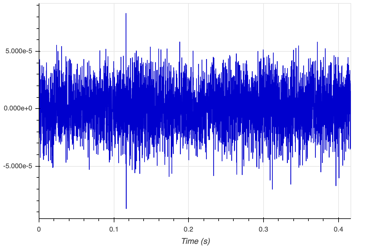
Of course you could do the same thing with Julia or other languages, if you wish, with obvious minor changes to the syntax!
17. Ranging and synchronization
org.arl.unet.Services.RANGING
It is common to use underwater acoustic modems for range estimation, as the travel time of acoustic signals can easily be measured. In
Section 2.3
, we saw that we can use the
range
command to estimate range between nodes. This command uses the RANGING service described below.
Ranging is closely related to time synchronization, since travel time measurement between two nodes requires some sort of synchronization between the nodes. If the nodes are synchronized, one-way travel time (OWTT) can be directly measured and used to estimate range. If the nodes are not synchronized, two-way travel time (TWTT) can be used to measure range and synchronize the nodes simultaneously. The RANGING service supports both modes of ranging, and manages synchronization information between nodes.
The RANGING service also supports ranging to commercial-off-the-shelf (COTS) transponders.
17.1. Overview
The RANGING service provides messages and parameters to support OWTT and TWTT ranging to other Unet nodes or COTS transponders, and to manage synchronization information between the nodes.
17.1.1. Messages
The following messages are defined by the RANGING service:
-
RangeReq⇒AGREE/REFUSE/FAILURE— measure range to peer node via OWTT or TWTT -
BeaconReq⇒AGREE/REFUSE/FAILURE— transmit beacon message for OWTT -
RangeNtf— sent when a range to another node is measured, typically in response toRangeReqon current node (sent to requester), orBeaconReqon peer node (sent to agent’s topic) -
InterrogationNtf— sent on agent’s topic when a ranging interrogration frame is recevied from peer, before a response is sent back -
RespondReq⇒AGREE/REFUSE— if automatic response is disabled, request to respond to interrogation frame (with optional payload)
The use of these messages will become clearer through examples below.
17.1.2. Parameters
The RANGING service does not define any parameters, but the default RANGING agent provides several useful parameters to control its behavior, and to provide status information.
17.2. Ranging agent
17.2.1. Parameters
A few parameters control the behavior of the default ranging agent:
In addition, the following parameters provide defaults for ranging:
-
channel— channel (DATA/CONTROL) to use for ranging -
maxRange— maximum expected range to peer (m) -
ipreamble— interrogation preamble to transmit -
rpreamble— response preamble to expect after interrogation -
rsignal— response baseband signal to expect after interrogation -
rdelay— response delay (seconds) -
threshold— threshold (0-1) for signal detection, when response is specified as an arbitrary acoustic signal
17.2.2. Indexed parameters
Some parameters can be additionally specified (or overridden) on a per-link basis, using indexed parameters (indexed by the node address of the peer node on the link):
-
address— peer node address -
channel— channel (DATA/CONTROL) to use for ranging -
maxRange— maximum expected range to peer (m) -
ipreamble— interrogation preamble to transmit -
isignal— interrogation baseband signal to transmit -
rpreamble— response preamble to expect after interrogation -
rsignal— response baseband signal to expect after interrogation -
rdelay— response delay (seconds) -
data— payload data to automatically include in response frame -
threshold— threshold (0-1) for signal detection, when response is specified as an arbitrary acoustic signal -
lifetime— synchronization validity lifetime (seconds)
The lifetime of syncrhonization information should be set based on the expected drift of modem clocks. Lifetime is defined as the time for the expected clock drift (scaled by speed of sound in water) to exceed the required range estimation accuracy. If a network uses modems with low-drift clocks (such as oven-controlled oscillators), the lifetime can be quite long (hours to days). Without low-drift clocks, reasonable lifetimes may only be in the order of several minutes to tens of minutes.
A few more read-only per-link parameters provide synchronization information about the link, when available:
17.3. Examples
In order to understand how the RANGING service provides OWTT and TWTT ranging, it is instructive to try a few examples using the Netiquette 3-node network simulation (
bin/unet samples/netq-network.groovy
). Start the simulation, and connect to node A:
> agentsForService(org.arl.unet.Services.RANGING)  (1)
[ranging]
> ranging
« Range estimator »

Provides time synchronization and range estimation services.

[org.arl.unet.localization.RangingParam]
  channel = 2                                      (2)
  ipreamble = 0
  mac = mac
  maxRange = 3000.0
  phy = phy
  rdelay = 1.95
  respond = true
  rpreamble = 0
  rsignal = []
  threshold = 0.3

> range host('B')                                  (3)
371.09
> ranging << new RangeReq(to: host('B'))           (4)
AGREE
ranging >> RangeNtf:INFORM[from:232 to:31 range:371.08856 offset:-1523892589 rxTime:1860655032]
> ntf.range
371.09| 1 |
We see that the
ranging
agent provides the RANGING service on the node.
|
| 2 | The DATA channel (channel 2) is being used for ranging. |
| 3 |
The
range
command provides us the range to node B of about 371 m.
|
| 4 |
The
range
command is implemented by sending a
RangeReq
to the
ranging
agent. We directly send that message. As expected, it leads to a
RangeNtf
message that gives us the same range estimate as the
range
command. The
RangeNtf
also provides us time synchronization information between the nodes (as time difference between the nodes, or
offset
, in microseconds).
|
17.3.1. Two-way travel time ranging
The range measurement above used TWTT ranging. While node B participated in the range measurement by responding to node A’s request for a two-way frame exchange, this is all done quietly and we see nothing on node B’s shell. To see what is happening on both nodes, subscribe to the
phy
and
ranging
agent’s topics on both nodes. Then repeat the
RangeReq
on node A:
> subscribe phy
> subscribe ranging
> ranging << new RangeReq(to: host('B'))
AGREE
phy >> TxFrameStartNtf:INFORM[type:DATA txTime:2048652195 txDuration:700]
phy >> RxFrameStartNtf:INFORM[type:DATA rxTime:2051086032]
phy >> RxFrameNtf:INFORM[type:DATA from:31 to:232 protocol:1 rxTime:2051086032 txTime:526951606 (7 bytes)]
ranging >> RangeNtf:INFORM[from:232 to:31 range:371.08856 offset:-1523892589 rxTime:2051086032]
We see that node A transmitted a DATA frame. It then received a timestamped DATA frame back from node B. The timing information in both frames was used to compute the range and time offset between the nodes. This was sent back to us as a
RangeNtf
. This is the frame exchange that implements TWTT ranging.
If we look at node B’s shell at the same time:
> subscribe phy
> subscribe ranging
phy >> RxFrameStartNtf:INFORM[type:DATA rxTime:525001443]
phy >> RxFrameNtf:INFORM[type:DATA from:232 to:31 protocol:1 rxTime:525001443 (1 byte)]
ranging >> InterrogationNtf:INFORM[type:DATA from:232 to:31 rxTime:525001443 responded:true]
phy >> TxFrameStartNtf:INFORM[type:DATA txTime:526951606 txDuration:700]
We see that node B received a DATA frame and responded back with a DATA frame. It generated a
InterrogationNtf
with
responded
set to
true
to indicate that it received an interrogation and responded to it. This is because
ranging.respond = true
, as seen above. If
ranging.respond
was set to
false
, the agent would have simply generated the
InterrogationNtf
without responding. This allows another agent to study the intorrogation, and optionally send back payload data as part of the response, using the
RespondReq
message.
17.3.2. Synchronization
We can ask node A for the synchronization information it has gathered from previous ranging exchanges:
> ranging[host('B')]
« RANGING »

[org.arl.unet.localization.RangingNodeParam]
  address ⤇ 31
  channel = 2
  data = []
  ipreamble = 0
  isignal = []
  lastSync ⤇ 1586070856974
  lifetime = 0
  maxRange = 3000.0
  offset = -1523892589
  rdelay = 1.95
  rpreamble = 0
  rsignal = []
  sync ⤇ false
  threshold = 0.3
We see that it has stored the time offset to node B, along with the information on when the synchronization information was last updated. However, you’ll find that the
sync
flag is
false
, since the
lifetime
parameter was set to 0, and hence the synchronization is considered expired. If you ask for synchronization information on node B, you’ll find that it does not have any:
> ranging[host('A')]
« RANGING »

[org.arl.unet.localization.RangingNodeParam]
  address ⤇ 232
  channel = 2
  data = []
  ipreamble = 0
  isignal = []
  lastSync ⤇ 0
  lifetime = 0
  maxRange = 3000.0
  offset = 0
  rdelay = 1.95
  rpreamble = 0
  rsignal = []
  sync ⤇ false
  threshold = 0.3
Without synchronization information, OWTT ranging cannot be performed.
If we have low-drift clocks on all our nodes, we can set the
lifetime
parameter for all the links to a larger value. Let’s do that on node A for link A-B. Also unsubscribe from
phy
to avoid too much clutter:
> ranging[host('B')].lifetime = 3600
3600
> unsubscribe phy
Now check the synchronization information for link A-B again:
> ranging[host('B')]
« RANGING »

[org.arl.unet.localization.RangingNodeParam]
  address ⤇ 31
  channel = 2
  data = []
  ipreamble = 0
  isignal = []
  lastSync ⤇ 1586070856974
  lifetime = 0
  maxRange = 3000.0
  offset = -1523892589
  rdelay = 1.95
  rpreamble = 0
  rsignal = []
  sync ⤇ true            (1)
threshold = 0.3| 1 |
We see that
sync
is now true, indicating that we have valid synchronization information on this link.
|
17.3.3. One-way travel time ranging
Now, let’s transmit a ranging beacon from node B:
> beacon      // equivalent to: ranging << new BeaconReq()
AGREE
On node A, we see
RangeNtf
from the OWTT ranging:
ranging >> RangeNtf:INFORM[from:232 to:31 range:371.08856 rxTime:1039174911]
Any timestamped frame transmission from node B will generate
RangeNtf
on node A now. This can be used to piggyback data (e.g. 42) along with the beacon:
phy << new TxFrameReq(timestamped: true, data: [42])
. This will generate a
RxFrameNtf
on node A, if you subscribe to
phy
, in addition to the
RangeNtf
messages. This works with both CONTROL and DATA frames.
|
17.3.4. Ranging to COTS transponders
The ranging agent provides a lot of flexibility for configuration. To see the power of this, let’s consider a scenario in which we want to use a UnetStack-based modem to measure range to a COTS transponder that is configured to respond to a 22 kHz 2 ms long pulse with a 30 kHz 2 ms pulse, after a delay of 30 ms.
| The example below is meant to run on a UnetStack-based modem. If you don’t have one, you can still try out the example on Unet audio and hear the interrogation pulse. However, because the default operating band of Unet audio SDOAM is 6-18 kHz, you’ll need to pick interrogation and response frequencies in this band. Also, you may want to make the interrogation pulse longer (say 200 ms), so you can hear it when you try ranging with this in air. |
First, we welcome the COTS transponder into our network as a Unet
guest
node by assigning it a name and address. Let’s call it node T with address
host('T') = 152
. On our modem node, we set up details of the link to the transponder:
> T = host('T')
152
> ranging[T].isignal = cw(22.kHz, 2.ms);
> ranging[T].rsignal = cw(30.kHz, 2.ms);
> ranging[T].rdelay = 30.ms;
> ranging
« RANGING »

[org.arl.unet.localization.RangingNodeParam]
  address ⤇ 152
  channel = 2
  data = []
  ipreamble = 0
  isignal = [0.0, -0.0, 0.8660254, -0.5, 0.5 ... 0.5, 0.8660254, 0.8660254, 0.5]
  lastSync ⤇ 0
  lifetime = 0
  maxRange = 3000.0
  offset = 0
  rdelay = 0.03
  rpreamble = 0
  rsignal = [0.0, 0.0, 6.123234E-17, 1.0, -1 ... 6022E-15, -3.1847007E-15, -1.0]
  sync ⤇ false
  threshold = 0.3
Now, we are all setup. To range to the transponder, all we need to do is:
> range T
235.7
Assuming you have the UnetStack-based modem in the water, along with the COTS transponder, you’ll get a range estimate back after just a short delay.
We have hardly scratched the surface of what the RANGING service and the ranging agent is capable of. There’s a lot you can do with it!
| For an example of how to build a simple long-baseline (LBL) navigation system with multiple nodes connected over wormholes amd ranging to a mobile node, see Chapter 11 . |
18. Node information
org.arl.unet.Services.NODE_INFO
The NODE_INFO service provides a single place to collate node-related information that is commonly needed by many agents. It is a special service, in the sense that each node must be configured to have one and only one agent providing this service.
18.1. Overview
An agent implementing the NODE_INFO service not only exposes a set of parameters, as described in this section, but also provides some special handling for specific parameters.
18.1.1. Parameters
An agent offering the NODE_INFO service supports several parameters:
-
nodeName— node name -
address— node address -
addressSize— address size in bits (valid values are 8 or 16) -
time— node time (read-only) -
canForward— true if the node will forward datagrams to other nodes (routing) -
origin— origin as (latitude, longitude) -
location— location as (x, y, z) in meters if origin set, otherwise (latitude, longitude, z) -
mobility— true if the node is mobile, false if it is fixed -
speed— speed in m/s, if mobile node -
heading— heading in degrees, 0 is North, measured clockwise -
pitch— pitch angle in degrees, 0 is level, positive is nose down -
roll— roll angle in degrees, 0 is level, positive is rolling starboard -
turnRate— turn rate in degrees/s, measured clockwise, if mobile node -
diveRate— dive rate in m/s, if mobile node
Any changes to parameters
nodeName
,
address
,
addressSize
,
origin
or
location
are published as
ParamChangeNtf
to the agent’s topic (in addition to the
PARAMCHANGE
topic that all parameter changes are automatically published to — see
Chapter 25
). This is to facilitate monitoring of changes to these important parameters by other agents, simply by subscribing to the NODE_INFO service provider’s topic.
Additionally, if time stability or location accuracy information is available, the following parameters are populated:
-
timeStability— time stability in ppm -
locationAccuracy— location accuracy as (x, y, z) in meters
18.1.2. Notes
-
See Section 4.1 for a discussion on
nodeName,addressandaddressSize. -
See Section 5.6 for a discussion on
origin,locationand coordinate systems. -
If node
mobilityis enabled, the agent may automatically updatelocationbased on motion parameters such asspeed,heading, etc.
18.2. Example
If you start the mission2013 network simulation (
bin/unet samples/mission2013-network.groovy
), connect to node 21’s shell and type
node
, you’ll see the NODE_INFO parameters for the node in this network:
> node
« Node information »

Manages and maintains node information and attributes.

[org.arl.unet.nodeinfo.NodeInfoParam]
  address = 232
  addressSize = 8
  canForward = true
  diveRate = 0
  heading = 0
  location = [0.0, 0.0, -15.0]
  mobility = false
  nodeName = A
  origin = [NaN, NaN]
  pitch = 0
  roll = 0
  speed = 0
  time ⤇ Thu Apr 08 20:43:40 SGT 2021
  turnRate = 0
19. Address resolution
org.arl.unet.Services.ADDRESS_RESOLUTION
19.1. Overview
An ADDRESS_RESOLUTION service provider is responsible for address allocation and resolution. The size of the address space is detemined by the
addressSize
parameter of the NODE_INFO service (
Chapter 18
).
19.1.1. Messages
Agents supporting this service honor the following requests:
-
AddressAllocReq⇒AddressAllocRsp/REFUSE/FAILURE— request for allocation of address to node -
AddressResolutionReq⇒AddressResolutionRsp/REFUSE/FAILURE— resolve node name to address
19.2. Usage and notes
Shell usage of this service via the
host
command is described in
Section 4.1
. In this section, we show examples of how address allocation and address resolution can be implemented directly by sending messages.
Address allocation is typically required at startup, and usually initiated by the agent providing the NODE_INFO service to populate the
address
parameter of that service. To ask the ADDRESS_RESOLUTION service provider to allocate an address, an agent sends it a
AddressAllocReq
. The allocation may depend on the node name, and so the request must contain the node name.
We can start the 2-node network, and manually test this on the shell of node A:
> a = agentForService(org.arl.unet.Services.ADDRESS_RESOLUTION);
> a << new AddressAllocReq(name: 'A')
AddressAllocRsp:INFORM[address:232]
Address resolution is performed via the
AddressResolutionReq
message. The
host
command sends this message on your behalf, and shows you the response:
> a << new AddressResolutionReq(name: 'A')
AddressResolutionRsp:INFORM[address:232 name:A]
> ans.address
232
> host('A')
232
While the address allocation and resolution processes may seem very similar, there is a conceptual difference between the two. Address allocation is performed for a new node without an address. The address allocation process associates it with an address. Address resolution is performed to find the address that was assigned to a node.
| The default ADDRESS_RESOLUTION service provider uses a hashing function to map node names to addresses. This enables it to allocate and resolve addresses without generating network traffic, as the hashing function generates the same address for a given name on each node. Because the hashing maps a large name space to a small address space, there is always the chance that two names map to the same address; we require that the network architect check this manually, and assign node names such that there are no address conflicts. |
| Network designers and protocol developers should not rely on the ADDRESS_RESOLUTION service provider being based on a hashing function for correct operation of the network. |
20. Medium access control
org.arl.unet.Services.MAC
20.1. Overview
Agents offering the medium access control (MAC) service advise other agents on when they may be permitted to make transmissions, in an effort to reduce collisions and improve network throughput.
MAC protocols that use PDUs for channel reservation may support piggybacking of client data in the PDU. If such support is available, it is advertised using a non-zero
reservationPayloadSize
parameter. A
ReservationReq
should provide the payload data to be sent to a peer node (as part of RTS or equivalent PDU) to whom the reservation is made. If that node wishes to send payload data back (as part of CTS or equivalent PDU), it may send a
ReservationAcceptReq
in response to a
ReservationStatusNtf
to provide its payload data.
| Protocol data units (PDUs) are protocol-specific datagrams exchanged by nodes in a network. MAC protocls that use a handshake often use three basic type of PDUs — request to send (RTS), clear to send (CTS) and acknowledgement (ACK). |
20.1.1. Messages
Agents supporting the MAC service provide messages to request, grant and cancel reservations:
-
ReservationReq⇒ReservationRsp/REFUSE— request a reservation -
ReservationCancelReq⇒AGREE/REFUSE— cancel a reservation -
ReservationAcceptReq⇒AGREE/REFUSE— request piggybacking of payload in a reservation PDU, typically sent by a client on receiving aReservationStatusNtf[status: REQUEST]notification -
TxAckReq⇒AGREE/REFUSE— request transmission of acknowledgement payload -
ReservationStatusNtf— sent to requestor or agent’s topic when a reservation-related events occur
While we use the term reservation for all MAC agents, it is important to understand that MAC agents are typically unable to guarantee that no other nodes transmit during the reservation period. The reservation is on a best-effort basis, and the probability of collision is dependent on the underlying MAC protocol in use. For example, a handshake-based MAC (using RTS/CTS) might be able to inform other nodes' MAC agents about a reservation, while carrier-sensing MAC agents may rely on hearing the transmission from another node to backoff reservations at their node. A MAC agent must, however, guarantee that no two agents on the same node are granted reservation at the same time.
Agents providing the MAC service are able to queue reservation requests from multiple agents, and grant reservations in order of arrival of request (or priority, or some other measure of fairness). It is, however, recommended that one agent only make one request to the MAC at a time, and submit its next request after the previous reservation is completed. An agent providing the MAC service may choose to refuse reservation requests from an agent that has pending reservation requests already in the queue.
20.1.2. Parameters
Agents offering the MAC service support the following parameters:
-
channelBusy— true if channel is busy, false otherwise -
reservationPayloadSize— maximum size of payload (bytes) that can be piggybacked in a reservation PDU -
ackPayloadSize— maximum size of acknowledgement (bytes) that can be included in an ACK PDU -
maxReservationDuration— maximum duration of reservation in seconds -
recommendedReservationDuration— recommended duration of reservation in seconds (null, if unspecified)
A MAC agent advertises the maximum supported reservation duration (
maxReservationDuration
), and must honor reservation requests for up to this duration. However, the network performance might suffer if all agents use very long reservations. To address this, the MAC agent also advertises a shorter recommendation for reservation duration (
recommendedReservationDuration
). Most agents should request reservations of this duration (or shorter) unless unavoidable.
20.1.3. Capabilities
Agents may support several optional capabilities:
An agent advertising this capability must be able to send acknowlegements as part of the MAC protocol. The agent must support the
TxAckReq
request to provide acknowledgement payload to be transmitted to the peer node at the end of the reservation. On reception, this payload should be delivered in the
ReservationStatusNtf[status: END]
on the peer node.
Agents advertising this capability must honor priority settings in the reservation request.
Agents advertising this capability must honor time-to-live settings in the reservation request.
Agents advertising this capability must support scheduling of reservations in the future, through the use of the
startTime
attribute of the
ReservationReq
.
20.2. Basic MAC functionality
MAC agents advise other agents that wish to transmit (we shall call them clients ) on when they may do so. MAC agents make channel reservations on behalf of their clients, as necessary. Some MAC protocols such as Aloha and TDMA may not require explicit handshake for reservation, while others such as MACA and FAMA may involve control packet exchanges between peer MAC agents on various nodes. In either case, a typical client with data to transmit starts by asking the prevailing MAC agent for a channel reservation:
// client wishes to transmit data to "destination" for specified "duration"
def mac = agentForService(Services.MAC)
if (mac) {
  def req = new ReservationReq(recipient: mac, to: destination, duration: duration) (1)
  def rsp = request(req)
  if (rsp && rsp.performative == Performative.AGREE) {
    def ntf = receive(ReservationStatusNtf, timeout)       (2)
    if (ntf && ntf.inReplyTo == req.messageID && ntf.status == ReservationStatus.START) {
      //    :
      // transmit data for requested duration
      //    :
    }
  }
}| 1 | Send a channel reservation request. |
| 2 | Wait for a channel reservation notification. |
In the above sample code, error handling has been omitted for simplicity. In reality, you would want to have else clauses to handle reservation failures. The MAC agent not only sends a
ReservationStatusNtf[status: START]
notification, but also a
ReservationStatusNtf[status: END]
notification at the end of the reservation duration. The sample code above ignores this notification, but a well-behaved client should ensure that the transmission does not exceed the requested duration.
20.3. Working with MAC payloads
Messages such as
ReservationReq
and
ReservationStatusNtf
may carry payloads, when the MAC protocol supports them. When payloads are supported, additional messages such as
ReservationAcceptReq
,
TxAckReq
and
TxAckNtf
are available for clients to provide payloads to the MAC service provider to piggyback on the MAC PDUs. A typical exchange is illustrated in
Figure 9
.
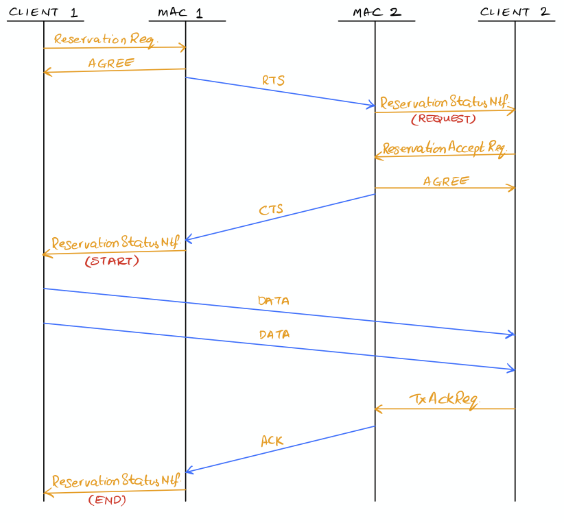
For a MAC reservation initiated by node A with node B, we elaborate on the steps for a full reservation lifecycle with payloads:
-
On node A, the client (agent) sends a
ReservationReqto the MAC (agent), with an optional payload. The MAC accepts the request. -
MAC on node A sends an RTS PDU with the payload to the MAC on node B.
-
MAC on node B generates a
ReservationStatusNtf[status: REQUEST]message and publishes it on its topic. A client subscribing to this topic receives the notification. -
If the client on node B wants to send back some payload with the CTS PDU, it immediately sends a
ReservationAcceptReqto the MAC, with the payload. -
The MAC accepts the request and responds to node A’s MAC with a clients PDU containing the payload.
-
The payload is delivered to the client on node A as part of a
ReservationStatusNtf[status: START]message marking the start of the reservation time. -
During the reservation, the two nodes exchange data as they wish.
-
If the client on node B wishes to provide an acknowledgment (with a payload), it sends a
TxAckReqmessage before the reservation duration ends, and the MAC on node B accepts. -
The MAC on node B sends an ACK PDU with the payload to the MAC on node A. The ACK PDU marks the end of the channel reservation. The MAC delivers this acknowledgment payload to the client on node A as a part of the
ReservationStatusNtf[status: END]message. -
If node B does not send an ACK PDU, when the channel reservation ends, the MAC on node A sends a
ReservationStatusNtf[status: END]message to its client.
20.4. Examples
Sample MAC implementations are illustrated in Chapter 29 .
21. Single-hop links
org.arl.unet.Services.LINK
21.1. Overview
Agents offering the LINK service provide single-hop communication.
Single-hop here refers to a single hop in the Unet sense. For example, a link may be provided over wireless RF network that has multiple physical hops (e.g. using UDP/IP). However, as long as the link does not pass through multiple Unet nodes, it is considered a logically single-hop link.
All agents supporting the LINK service must also support the DATAGRAM service ( Chapter 14 ).
It is recommended that agents offering the LINK service provide reliability, when requested. Agents that are able to provide reliability, do so by advertising the DATAGRAM service capability RELIABILITY.
LINK service providers using the PHYSICAL service should also consult the MAC service to determine when they should transmit.
In a typical Unet, gateway nodes may have several LINK service providers, with the ROUTING service ( Section 22.2 ) provider forwarding datagrams across links.
21.1.1. Messages
The LINK service defines only one optional message, used only by agents advertising the LINK_STATUS capability.
-
LinkStatusNtf— link up/down or quality notification
21.1.2. Parameters
Agents offering the LINK service may support the following parameter:
-
dataRate— nominal data rate of link in bps (0 if unknown)
21.1.3. Capabilities
Agents may support several optional capability:
Agents advertising this capability will send
LinkStatusNtf
messages on its topic, when a link becomes active, is lost, or has significant change in quality.
21.2. ReliableLink
Start the 2-node network and connect to node A:
> agentsForService org.arl.unet.Services.LINK
[uwlink]

> uwlink
« Reliable acoustic link »

Link protocol with support for reliability and fragementation-reassembly.

[org.arl.unet.DatagramParam]
  MTU ⤇ 848
  RTU ⤇ 848

[org.arl.unet.link.LinkParam]
  dataRate ⤇ 731.4286

[org.arl.unet.link.ReliableLinkParam]
  acks = 2
  controlChannel = 1
  dataChannel = 2
  mac = mac
  maxPropagationDelay = 2.5
  maxRetries = 2
  phy = phy
  reservationGuardTime = 0.5

> uwlink << new CapabilityReq()
CapabilityListRsp:INFORM[FRAGMENTATION,RELIABILITY,LINK_STATUS]
We see that in the 2-node network simulation, the only agent that provides the link service is the
uwlink
agent of type
ReliableLink
. This agent fragments large datagrams, and transmits a batch of frames at a time, before waiting for an acknowledgement from the peer node. Unacknowledged frames are retransmitted until all frames are delivered, or there are too many retries. Once all frames are received, the peer node’s
uwlink
agent reassembles the datagram and delivers it. The agent also provides link status notifications.
ReliableLink
provides the LINK service for all underwater links in Unet basic stack that ships as part of the community edition.
|
With the default PHYSICAL service settings, the nominal data rate provided by this link is 731 bps, and that only 848 or less bytes may be transferred per datagram. The actual data rate may differ, depending on the size of the datagram, reliability settings, and the channel conditions.
We also see that
ReliableLink
provides a set of configurable parameters:
-
acks -
Number of acknowledgements to use for reliable data transfer. Since a lost acknowledgement frame results in retransmission of the entire batch of frames, multiple acknowledgements are used to improve the robustness of the acknowledgement frame.
-
controlChannel -
Frame type to use for control information. This is usually the CONTROL frame type.
-
dataChannel -
Frame type to use for data frames. This is usually the DATA frame type.
-
mac -
MAC service provider to use for reserving the channel. This is automatically discovered during startup. Setting this to
nulldisables MAC reservation. -
maxPropagationDelay -
Maximum expected propagation delay for the link (in seconds). This should be set based on the expected single-hop communication range, and the sound speed (in case of acoustic links). This parameter is used to determine expected round-trip time for setting timeouts for acknowledgement frames.
-
maxRetries -
Maximum number of retries per frame. Once the maximum number of retries is exceeded, a datagram transfer is deemed to have failed.
-
phy -
PHYSICAL service provider for data transmission. This is automatically discovered during startup, but may be configured manually on gateway nodes with multiple PHYSICAL service providers.
-
reservationGuardTime -
Guard time (in seconds) that is included in a MAC reservation of the channel. The guard time allows for small timing variability in transmission and small delays in response from peer node.
21.3. ECLink
In the Unet premium stack,
ECLink
replaces
ReliableLink
as the default LINK service provider for underwater links.
|
ECLink
uses an erasure correction code (type of error correction code that deals with lost frames) to reduce the protocol overhead required for retransmissions in a lossy channel. This usuaully results in significantly better performance than
ReliableLink
in poor channel conditions, and when transferring large datagrams.
If you have a modem with the commercial version of UnetStack3, it’ll have
ECLink
loaded as the default LINK service provider:
> uwlink
« Erasure coded link »

Link protocol based on erasure coding, for fast large data transfers over a single hop.

[org.arl.unet.DatagramParam]
  MTU ⤇ 3145584
  RTU ⤇ 1450

[org.arl.unet.link.ECLinkParam]
  compress = true
  controlChannel = 1
  dataChannel = 2
  mac = mac
  maxBatchSize = 65533
  maxPropagationDelay = 3.0
  maxRetries = 2
  minBatchSize = 3
  phy = phy
  reliability = false
  reliableExtra = 0.2
  unreliableExtra = 0.3

[org.arl.unet.link.LinkParam]
  dataRate ⤇ 731.4286

> uwlink << new CapabilityReq()
CapabilityListRsp:INFORM[COMPRESSION,RELIABILITY,CANCELLATION,FRAGMENTATION,LINK_STATUS]
We see that the
MTU
for
ECLink
is quite large (as compared to
ReliableLink
), as
ECLink
can efficiently transfer large amounts of data. While the
dataRate
parameter advertises a similar nominal rate as with
ReliableLink
, you’ll find that
ECLink
yields better practical performance when transferring large files, and in poor channel conditions.
ECLink
also supports data compression, and link status notifications.
The
phy
,
controlChannel
,
dataChannel
,
mac
,
maxRetries
, and
maxPropagationDelay
parameters of
ECLink
are similar to the ones in
ReliableLink
. However,
ECLink
has several additional parameters that control performance:
-
minBatchSize -
Minimum number of frames to send in each batch.
-
maxBatchSize -
Maximum number of frames to send in each batch.
-
reliability -
Default reliability for a datagram transfer, if a
DatagramReqdoes not specify reliability (null). -
reliableExtra -
Fraction of extra frames to transmit for erasure correction, during reliable datagram transfer (using acknowledgements to determine retries). A value of 0.2 indicates 20% extra frames are transmitted. This allows for 20% frame loss without the need for retries.
-
unreliableExtra -
Fraction of extra frames to transmit for erasure correction, during unreliable datagram transfer (no acknowledgement or retries). A value of 0.3 indicates 30% extra frames are transmitted. This allows for successful datagram transfer with as much as 30% frame loss.
-
compress -
Enable/disable data compression.
22. Routing and route maintenance
22.1. Overview
The ROUTING and ROUTE_MAINTENANCE services work closely to provide multi-hop communications. The ROUTING serice provider is responsible for maintaining a routing table, and for routing datagrams according to the table. The ROUTE_MAINTENANCE service provider, on the other hand, is responsible for discovering new routes and providing updated routing information to the ROUTING service provider.
If a network only requires static routes, the ROUTING service provider is sufficient to provide the functionality. In case of networks with dynamic route discovery, a ROUTE_MAINTENANCE service provider discovers routes (or route changes) and publishes
RouteDiscoveryNtf
messages. The ROUTING service provider subscribes to these messages and updates its routing tables.
The ROUTING service provider also typically listens for
LinkStatusNtf
messages from the LINK service agents. These messages allow it to keep track of link availability and link quality.
Both ROUTING and ROUTE_MAINTENANCE services are described below.
22.2. Routing service
org.arl.unet.Services.ROUTING
Agents offering the ROUTING service provide multi-hop communication.
All agents supporting the ROUTING service must also support the DATAGRAM service ( Chapter 14 ).
It is recommended that agents offering the ROUTING service provide reliability, when requested. Agents that are able to provide reliability, do so by advertising the DATAGRAM service capability RELIABILITY.
22.2.1. Messages
Agents providing the ROUTING service support the following messages:
-
GetRouteReq⇒RouteRsp/AGREE/REFUSE— find route or a list of routes -
EditRouteReq⇒AGREE/REFUSE— add, delete or change routing table entry -
RouteChangeNtf— sent to agent’s topic when a routing table entry is added, removed or changed
The
GetRouteReq
message may be used to request a single route (
all = false
), or a list of routes (
all = true
). When a single route is requested, the response is either a
RouteRsp
(with route information) or a
REFUSE
(if no route available). When multiple routes are requested, the response is a series of
RouteRsp
messages, followed by an
AGREE
message to indicate end of the list. If no routes available, a
REFUSE
message is sent back instead of the
AGREE
message.
While the above messages may be used programmatically to manipulate the routing table, typically users interact with the router via the shell commands described in Chapter 6 and Section 22.4 below.
22.3. Route maintenance service
org.arl.unet.Services.ROUTE_MAINTENANCE
Agents offering the ROUTE_MAINTENANCE service generate
RouteDiscoveryNtf
messages to allow ROUTING service providers to maintain routing tables.
22.3.1. Messages
Agents providing the ROUTE_MAINTENANCE service support the following messages:
-
RouteDiscoveryReq⇒AGREE/REFUSE/FAILURE— start route discovery to a specified node -
RouteTraceReq⇒AGREE/REFUSE/FAILURE— trace current route to a specified node -
RouteDiscoveryNtf— sent to the agent’s topic when a route is discovered -
RouteTraceNtf— sent to requestor when a requested trace is successfully completed
22.4. Router and the route discovery protocol
The
Router
class (agent name
router
) provides the ROUTING service in the standard stack. Apart from supporting the
routes
,
addroute
,
delroute
and
delroutesto
commands, this agent exposes two parameters:
-
auto1hop— automatically assume single-hop routes available, if no entry for destination node in routing table -
defaultLink— default LINK service provider to use for datagram transmission, if unspecified while adding a route
Without
auto1hop
enabled, every route must be explicitly added to the routing table (even when the node is accessible over a single hop). By enabling
auto1hop
, we tell the router than any node that isn’t explicitly added to the routing table is assumed to be accessible over a single hop. This is the default setting:
> router
« Router »

Routes datagrams in the network, based on a routing table.

[org.arl.unet.DatagramParam]
  MTU = 3145581
  RTU = 1447

[org.arl.unet.net.RouterParam]
  auto1hop = true
  defaultLink = uwlink
The
RouteDiscoveryProtocol
class (agent name
rdp
) provides the ROUTE_MAINTENANCE service in the standard stack. This agent has no configurable parameters.
In
Chapter 6
, we explored several examples of how to set up networks with static and dynamic routes. To find out more about routing, type
help router
in the shell:
> help router
router - access to routing service

Examples:
  routes              // display routing table
  routes 2            // display routes to node 2
  addroute 27, 29     // add a route to node 27 via node 29
  delroute 'as7623'   // delete route with UUID as7623
  editroute 'as7623', metric: 5.0 // edit route to change metric
  delroutesto 27      // delete all routes to node 27
  delroutes           // delete all routes
  trace 27            // trace route to node 27
  ping 27             // check if node 27 is accessible

Parameters:

- router.MTU - maximum data transfer size
- router.RTU - recommended data transfer size
- router.auto1hop - automatically assume single hop routes
- router.defaultLink - default link to use

Commands:

- routes - print routing table
- addroute - add a route to the routing table
- editroute - edit a route in the routing table
- delroute - delete a route from the routing table
- delroutesto - delete all routes to specified node from the routing table
- delroutes - delete all routes from the routing table
You can also type
help
followed by any of the commands above to get more information on the usage of that command.
23. Transport service
org.arl.unet.Services.TRANSPORT
23.1. Overview
Agents offering the TRANSPORT service provide end-to-end reliability and fragmentation/reassembly for large datagrams. They may also support connection-oriented services for data streaming. Agents providing this service typically use the ROUTING service for multi-hop delivery of data.
All agents supporting the TRANSPORT service must also support the DATAGRAM service ( Chapter 14 ), along with the RELIABILITY and FRAGMENTATION capabilities. It is also recommended that they support the CANCELLATION and PROGRESS capabilities, since datagrams at this level are likely to be large.
There are no special messages or parameters defined by the TRANSPORT service, but agents providing this service may expose additional parameters to configure the transport protocol in use.
23.2. Stop-and-wait transport
The default implementation of the TRANSPORT service is the
SWTransport
class. If you start the 2-node network simulation and connect to node A, you can explore the configurable parameters that it advertises:
> transport
« Stop-and-wait transport »

Multi-hop transport service based on the stop-and-wait protocol.

[org.arl.unet.DatagramParam]
  MTU ⤇ 16777215
  RTU ⤇ 16777215

[org.arl.unet.transport.SWTransportParam]
  dsp = router
  maxHops = 3
  maxRetries = 2
  reportProgress = false
  timeoutPerHop = 90.0
We briefly explain each parameter below:
-
dsp -
Datagram service provider. This is the agent that is used to deliver datagrams. Using
routerfor this parameter enables multi-hop networks. -
maxHops -
Maximum number of hops expected to destination nodes.
-
maxRetries -
Maximum number of end-to-end retries, if end-to-end acknowledgements are not received. We recommend that link level reliability be enabled to reduce end-to-end retries. This is easily done by setting the
reliabilityparameter for a route, or by enablingreliabilityat the LINK service provider (if it offers such a parameter). -
reportProgress -
Setting this parameter to
trueasks thetransportagent to send out periodicDatagramProgressNtfmessages to the requester (on the transmitting node) or on the agent’s topic (on the receiving node), when transferring large datagrams. -
timeoutPerHop -
Timeout (in seconds) per hop, for datagram transfer.
Next, let’s try a 2048-byte datagram transfer from node A to node B with progress reports:
> transport.reportProgress = true;
> transport << new DatagramReq(to: 31, data: new byte[2048], reliability: true)
AGREE
transport >> DatagramProgressNtf:INFORM[id:2 to:31 to:(838/2048 bytes, 40%)]
transport >> DatagramProgressNtf:INFORM[id:2 to:31 to:(1676/2048 bytes, 81%)]
transport >> DatagramProgressNtf:INFORM[id:2 to:31 to:(2048/2048 bytes, 100%)]
transport >> DatagramDeliveryNtf:INFORM[id:d76a56bf-58f6-4a9c-8a19-7a0a6ce8bcd4 to:31]
The entire transfer will take a few minutes. During that time, we get periodic
DatagramProgressNtf
reports showing how much of the data transfer was completed.
24. Remote access
org.arl.unet.Services.REMOTE
24.1. Overview
Agents offering the REMOTE service provide text messaging, file transfer, and remote command execution services across a network.
| While the REMOTE service provides a field for credentials to be included in a request, it does not specify how authentication and security should be handled by an agent. It is important for developers and users of the REMOTE service to give due consideration to network security before enabling this service on their network. |
24.1.1. Messages
Agents providing the REMOTE service support the following messages:
-
RemoteTextReq⇒AGREE/REFUSE/FAILURE— send a text message to remote node -
RemoteFileGetReq⇒AGREE/REFUSE/FAILURE— download a file from remote node -
RemoteFilePutReq⇒AGREE/REFUSE/FAILURE— upload a file to remote node -
RemoteExecReq⇒AGREE/REFUSE/FAILURE— execute a shell command on the remote node -
RemoteTextNtf— sent to the agent’s topic when a text message from another node arrives -
RemoteFileNtf— sent to the agent’s topic when an incoming file transfer from another node is completed -
RemoteSuccessNtf— sent to a requester when a remote operation is successfully completed, if an acknowledgement was requested -
RemoteFailureNtf— sent to a requester when a remote operation fails, if an acknowledgement was requested
24.2. RemoteControl
Start the 2-node network and connect to node A:
> agentsForService org.arl.unet.Services.REMOTE
[remote]
> remote
« Remote control »

Text messaging and remote command execution service.

[org.arl.unet.remote.RemoteControlParam]
  cwd = /Users/mandar/tmp/unet-3.2.0/scripts
  dsp = transport
  enable = false
  groovy = true
  reliability = true
  shell = websh
We see that the REMOTE service is provided by the
remote
agent of type
RemoteControl
. The agent’s behavior is controlled by several parameters:
-
cwd -
Current working directory. This directory is the reference location for all file transfers and command execution.
-
dsp -
Datagram service provider. This is the agent that is used to deliver datagrams.
-
shell -
SHELL service provider (see Chapter 27 ) used to execute commands. When a remote command is to be executed, a request is sent to this shell agent to execute the command.
-
groovy -
Enable Groovy extensions for shell commands. This should only be enabled if the
shellis a Groovy shell. The only Groovy extension defined at this point in time is the?shortcut. Starting a command with a?automatically sends the output of the command back to the requesting node (e.g.?phy.MTUis equivalent totell me, phy.MTU as String). We have encountered the use of this extension before in Section 5.5 . -
reliability -
Setting this to
trueenablesreliabilityfor all datagrams used by the agent. -
enable -
Setting this to
trueenables incoming remote file operations and remote commands. The parameter isfalseby default, for security reasons. Outgoing remote operations are always enabled, irrespective of this parameter. Incoming and outgoing text messaging is also always enabled when this agent is loaded.
The default
RemoteControl
agent in the basic stack does not implement any authentication. Once enabled, it will accept all file transfer and remote command execution requests. Care should be taken not to
enable
it in networks where malicious hackers may be able to send harmful requests to your node.
|
The
phy[CONTROL].scrambler
and
phy[DATA].scrambler
parameters available in many UnetStack-based modems provide a basic level of protection against malicious hackers by scrambling each transmission in the modem. Setting the
scrambler
to a "secret" value (64-bit key) in all your nodes enables this basic protection. Do bear in mind that scrambling is not a crypotgraphically strong technique, and will not protect you from a serious hacker. The technique is also vulnerable to playback attack, even if the malicious hacker is unable to unscramble your frame.
|
All remote commands (
tell
,
fget
,
fput
,
rsh
, and
ack
) encountered in
Section 5.4
and
Section 5.5
are implemented by the shell using the above messages. For example, the same effect as the
tell
command can be achieved by directly sending the
RemoteTextReq
message to the
remote
agent on node A:
> remote << new RemoteTextReq(to: host('B'), text: 'hello!', ack: true)
AGREE
remote >> RemoteSuccessNtf:INFORM[RemoteTextReq:REQUEST[to:31 text:hello! ack:true]]
We should see the text message delivered on node B:
[232]: hello!
We encourage you to re-read
Section 5.5
and explore the command’s help documentation (
help remote
) to fully appreciate the use of this service.
25. State persistence
org.arl.unet.Services.STATE_MANAGER
25.1. Overview
An agent offering the STATE_MANAGER service provides a way to save the state (parameter values) of specified (or all) agents.
Such an agent typically subscribes to the
PARAMCHANGE
topic and monitor
ParamChangeNtf
for all parameter changes for all agents. It then helps persist selected agents' parameter values between reboots.
25.1.1. Messages
STATE_MANAGER service providers honor the following messages:
-
SaveStateReq⇒AGREE/REFUSE/FAILURE— save agent state to a file -
ClearStateReq⇒AGREE/REFUSE/FAILURE— clear agent state in memory, and track only parameter changes henceforth
The
SaveStateReq
message causes the agent state (changed parameters) to be persisted to a Groovy script file in the
scripts
folder. The default name of the file is
saved-state.groovy
, and this file is automatically loaded on startup. However, the
SaveStateReq
message can specify an alternate filename to persist the state in. In such cases, the file is run manually when the state is to be restored.
25.2. Examples
Fire up Unet audio (
bin/unet audio
) to test out how state persistence works:
> plvl
phy[1].powerLevel = -42.0
phy[2].powerLevel = -42.0
phy[3].powerLevel = -42.0
phy[4].powerLevel = -42.0
phy.signalPowerLevel = -42.0
> plvl -40
OK
> shutdown
Now start Unet audio again, and you’ll find that the
plvl
state was not retained through reboots:
> plvl
phy[1].powerLevel = -42.0
phy[2].powerLevel = -42.0
phy[3].powerLevel = -42.0
phy[4].powerLevel = -42.0
phy.signalPowerLevel = -42.0
We can ask it to retain the state:
> plvl -40
OK
> savestate (1)
AGREE
> ls
README.md [759 bytes]
saved-state.groovy [156 bytes] (2)
> shutdown| 1 |
The
savestate
command just sends a
SaveStateReq
message to the STATE_MANAGER service provider.
|
| 2 |
The
saved-state.groovy
file is created with all the parameter changes to all agents.
|
Start Unet audio again, and you’ll find that the state is retained:
> plvl
phy[1].powerLevel = -40.0
phy[2].powerLevel = -40.0
phy[3].powerLevel = -40.0
phy[4].powerLevel = -40.0
phy.signalPowerLevel = -40.0
> shutdown
The
saved-state.groovy
is human-readable, and you’ll see that it simply contains the Groovy code to set the parameters required to restore the state:
def phy = agent('phy')
phy[1].powerLevel = -40.0
phy[2].powerLevel = -40.0
phy[3].powerLevel = -40.0
phy[4].powerLevel = -40.0
phy.signalPowerLevel = -40.0Delete this file and start Unet audio again:
> help savestate
savestate - save state of all or specified agent in Groovy script format
Examples:
savestate 'pandan' // save current state of all agents
savestate 'pandan', 'phy' // save current state of specified agent
savestate 'pandan', phy // save current state of specified agent
savestate // save current state in "saved-state.groovy"
> help clrstate
clrstate - set current state as the baseline for savestate
Example:
clrstate // set baseline state
phy[1].powerLevel = -10 // change parameters
savestate // save changed parameters
The help shows you that the
savestate
command can be used to save the state of individual agents, if you wish, to a filename of your choice. If you save the state to a different filename, it is not automatically restored on startup. But you can restore it easily with a single command (name of the file):
> plvl
phy[1].powerLevel = -42.0
phy[2].powerLevel = -42.0
phy[3].powerLevel = -42.0
phy[4].powerLevel = -42.0
phy.signalPowerLevel = -42.0
> plvl -40
OK
> savestate 'p40', phy (1)
AGREE
> plvl -10 (2)
OK
> ls
README.md [759 bytes]
p40.groovy [156 bytes] (3)
> p40 (4)
> plvl
phy[1].powerLevel = -40.0
phy[2].powerLevel = -40.0
phy[3].powerLevel = -40.0
phy[4].powerLevel = -40.0
phy.signalPowerLevel = -40.0| 1 |
Save the
plvl -40
state to a file called
p40.groovy
.
|
| 2 | Change the state. |
| 3 |
The state is saved in the
p40.groovy
file in the
scripts
folder.
|
| 4 |
Command
p40
runs the
p40.groovy
file to restore the state to
plvl -40
.
|
26. Scheduler
org.arl.unet.Services.SCHEDULER
26.1. Overview
Agents offering the SCHEDULER service provide a way to schedule sleep/wake tasks in the future.
26.1.1. Messages
The following messages are used by the SCHEDULER service:
-
AddScheduledSleepReq⇒AGREE/REFUSE/FAILURE— add a new scheduled sleep -
RemoveScheduledSleepReq⇒AGREE/REFUSE/FAILURE— remove a scheduled sleep -
GetSleepScheduleReq⇒AGREE/REFUSE/FAILURE— get all the scheduled sleep/wake times -
WakeFromSleepNtf— sent to agent’s topic just after node wakes up from a sleep
26.2. Sleep/wake scheduling
The Unet simulator currently does not support sleep/wake scheduling. While Unet audio supports the SCHEDULER service, it does not actually put your computer to sleep. Therefore you can experiment with creating and managing schedules on Unet audio, without worrying about your computer going to sleep. Start up Unet audio (
bin/unet audio
) and connect to its shell:
> agentsForService org.arl.unet.Services.SCHEDULER
[phy]
> phy.rtc
Sun Sep 22 02:58:20 SGT 2019
> help scheduler
scheduler - access to scheduling service
Commands:
- addsleep - schedule sleep and wakeup of the modem
- showsleep - shows sleep/wakeup schedule
- rmsleep - removes sleep/wakeup schedule
> help addsleep
addsleep - schedule sleep and wakeup of the modem
Examples:
addsleep 1507014548, 1507014558 // sleep from epoch 1507014548 to 1507014558
addsleep 1507014558 // sleep immediately until 1507014548
addsleep 10.s.later, 20.s.later // sleep 10s later and wake up 20s later
addsleep 20.s.later // sleep immediately and wake up 20s later
addsleep 20.s.later, forever // sleep 20s later forever
addsleep // sleep immediately forever
> addsleep 1.hour.later, forever
AGREE
> showsleep
bbfb3b79-942c-4fba-bc37-ab9d18dabda5: Sun Sep 22 04:00:00 SGT 2019 to eternity
> rmsleep 'bbfb3b79-942c-4fba-bc37-ab9d18dabda5'
AGREE
> showsleep
> addsleep 1.hour.later, 2.hours.later
AGREE
> showsleep
87de2dec-db29-4b34-a93c-775bfe8c68c5: Sun Sep 22 04:02:36 SGT 2019 to Sun Sep 22 05:02:36 SGT 2019
We see that the
phy
agent provides the SCHEDULER service in Unet audio. We add a sleep schedule, check that it shows up, remove it, and check that it is deleted. We then add another schedule.
The
addsleep
,
showsleep
, and
rmsleep
commands use the
AddScheduledSleepReq
,
GetSleepScheduleReq
, and
RemoveScheduledSleepReq
messages to achieve their functionality. We can manually send this messages to confirm this, if we like:
> phy << new GetSleepScheduleReq()
SleepScheduleRsp:INFORM[(1 item)]
> ans.sleepSchedule
[87de2dec-db29-4b34-a93c-775bfe8c68c5: Sun Sep 22 04:02:36 SGT 2019 to Sun Sep 22 05:02:36 SGT 2019]We can also use the web interface to manage the sleep schedule, if we like:
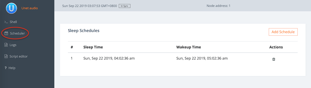
A big advantage of working with the web interface for sleep scheduling is that the user interface displays date/time in a human readable format. On the other hand, programmatic access with messages requires times to be specified as Unix epoch time.
26.3. Epoch time
The Unix epoch is the number of seconds that have elapsed since January 1, 1970 (midnight UTC), not counting leap seconds. While computers find it easy to work with epoch time, we find it hard to interpret. So UnetStack introduces syntactic sugar such as "1.hour.later" that computes the Unix epoch time 1 hour from now:
> 1.hour.later
1569097078
> 2.minutes.later
1569093616There are online calculators that’ll help you convert between Unix epoch time and human readable date/time. This works well, if you need to manually convert a few date/times, but what if you needed to do this programmatically? Java provides simple APIs to deal with date/times:
> import java.time.Instant
> Instant.now().epochSecond (1)
1569094526
> Instant.ofEpochSecond(1569093616) (2)
2019-09-21T19:20:16Z
> Instant.parse("2019-09-21T19:20:16Z").epochSecond (3)
1569093616| 1 | Get current epoch time. |
| 2 | Convert epoch time to human readable time in UTC. |
| 3 | Convert human readable time in UTC to epoch time. |
If you want even nicer looking date/time strings, you should check out Java’s SimpleDateFormat class.
27. Shell
org.arl.fjage.shell.Services.SHELL
The SHELL service provides a way to run commands and access files on a node. It is used by agents providing the REMOTE service to support remote execution of commands from other nodes.
27.1. Overview
Agents providing the SHELL service support execution of commands, and access to files on the node. While shell agents typically provide interactivity using a terminal/console, they also support messages for other agents to request execution of commands or access to files.
27.1.1. Messages
-
ShellExecReq⇒AGREE/REFUSE/FAILURE— execute a command -
GetFileReq⇒FileGetRsp/REFUSE/FAILURE— read a file or directory contents -
PutFileReq⇒AGREE/REFUSE/FAILURE— write contents to a file, or delete a file
27.2. Script engines
The language in which the commands are written is not defined by the service, but depends on the shell agent. fjåge supports a pluggable mechanism for an
ShellAgent
to use any
ScriptEngine
. Various script engines are available in fjåge and UnetStack, including the
GroovyScriptEngine
,
EchoScriptEngine
, and
ATScriptEngine
.
27.3. Examples
Start the 2-node network and connect to node A:
> agentsForService org.arl.fjage.shell.Services.SHELL (1)
[websh]
> websh.send new ShellExecReq(cmd: 'file("foobar").text = "FOOBAR";') (2)
websh >> AGREE
> ls (3)
foobar [6 bytes]
README.md [759 bytes]
> file("foobar").text (4)
FOOBAR| 1 |
We find that
websh
is the agent that provides us the SHELL service.
|
| 2 |
We send a command to
websh
to execute, and it agrees to do so. Since the commands we type are also executed by the
websh
agent, we need to be careful to not block the execution. Hence we use a
send
rather than a
request
(or equivalently
<<
).
|
| 3 |
The command was to create a
foobar
file, so we check that the file is created.
|
| 4 |
We read the contents of the
foobar
file to confirm that
FOOBAR
was correctly written to it.
|
Next, let’s try the
GetFileReq
and
PutFileReq
messages to read, write and delete this file:
> websh.send new GetFileReq(filename: 'scripts/foobar') (1)
websh >> INFORM: GetFileRsp
> ntf.contents (2)
[70, 79, 79, 66, 65, 82]
> new String(ntf.contents) (3)
FOOBAR
> websh.send new PutFileReq(filename: 'scripts/foobar', contents: 'foooobaaaar')
websh >> AGREE (4)
> file('foobar').text (5)
foooobaaaar
> websh.send new PutFileReq(filename: 'scripts/foobar', contents: null)
websh >> AGREE (6)
> ls
README.md [759 bytes]
> websh.send new GetFileReq(filename: 'scripts') (7)
websh >> INFORM: GetFileRsp
> new String(ntf.contents)
README.md 759 1568297372000 (8)| 1 |
The file
foobar
was created in the
scripts
folder, which is the default location for the
file()
function. We ask to read the file, and get a
GetFileRsp
response back.
|
| 2 | The file contents are read back as a list of bytes. |
| 3 |
We convert the list of bytes to a String to get our
FOOBAR
contents.
|
| 4 |
We send a
PutFileReq
to change the contents of the file.
|
| 5 | We verify that the file contents were indeed changed, as requested. |
| 6 |
Sending a
PutFileReq
with
contents
set to
null
deletes the file.
|
| 7 |
Asking for the contents of a directory using
GetFileReq
gets us the directory listing back.
|
| 8 |
The listing consists of all files in the directory, one file per line. Each line has a filename, file size and file modificiation timestamp (epoch time). If a file is a directory, the filename is suffixed by a
/
.
|
We interacted with the SHELL service provider using a shell! That’s not very useful in practice, but served to show you how these messages work. Typically, these messages are sent by other agents that wish to get the shell to run commands and access files for them (e.g.
RemoteControl
agent in
Section 24.2
). The agents may be running remotely in a fjåge slave container or on a gateway (via the UnetSocket API), where they may not have direct access to the filesystem of the node.
Part V: Extending UnetStack
28. Developing your own agents
By now, you should be very familiar with the concept of agents. You have interacted with them via commands and messages throughout this handbook, but what exactly is an agent?
If you lookup the Wikipedia entry for a software agent, you’ll find:
The term agent describes a software abstraction, an idea, or a concept, similar to object-oriented programming terms such as methods, functions, and objects. The concept of an agent provides a convenient and powerful way to describe a complex software entity that is capable of acting with a certain degree of autonomy in order to accomplish tasks on behalf of its host. But unlike objects, which are defined in terms of methods and attributes, an agent is defined in terms of its behavior.
retrieved 8 September 2019
In this chapter, we take this somewhat abstract concept and crystallize it by developing a simple agent. While the idea of writing your own agent might sound daunting at first, you’ll soon see that it is actually quite easy!
28.1. Unet agents
Agents are the basic building blocks of the UnetStack. They exchange messages, provide services and implement protocols. While what is expected from a well-behaved agent is quite demanding, most of the necessary core behaviors are already implemented for you by the
UnetAgent
base class. All you need to do is to extend it, and add in a little code to teach the agent what you want it to do.
| While you have the option of writing agents in Java or Groovy (or any other language running on the Java VM), we recommend writing agents in Groovy, as Groovy agents tend to need less biolerplate code and are more readable and maintainable. They are also easier to test as Groovy classes can be dynamically loaded from source, without having to pre-compile them. However, if you are already an expert in Java and prefer to use it, you’re welcome to do so. |
The basic skeleton of a Groovy agent looks like this:
import org.arl.fjage.*
import org.arl.unet.*
class MyAgent extends UnetAgent {
@Override
void setup() {
// this method is called when the stack is initialized
// register services and capabilities that you provide here
}
@Override
void startup() {
// this method is called just after the stack is running
// look up other agents and services here, as needed
// subscribe to topics of interest to get notifications
}
@Override
Message processRequest(Message msg) {
// process requests supported by the agent, and return responses
// if request is not processed, return null
return null
}
@Override
void processMessage(Message msg) {
// process other messages, such as notifications here
// if a message is not interesting, it can be safely just ignored
}
}
While you don’t strictly need the
@Override
annotations, it is a good practice to use them whenever you are overriding a method from a superclass. The annotation tells the compiler that this is what you intend, and so if you make a typographical mistake and type in a wrong method name (one that doesn’t exist in the superclass), the compiler will warn you.
If you do not need any of these methods, you can skip the definition as the base class provides default implementations. There are a several other methods that you can override to customize your agent, but these are less commonly needed and so we’ll skip them for now. You’ll come across them later.
If you happen to be already familiar with the
fjåge agent lifecycle
, you may wish to note that the
setup()
method is called from the
init()
method of the agent. The
startup()
method is called from a one-shot behavior scheduled during initialization. The
processRequest()
and
processMessage()
methods are called from a message behavior added during initialization.
|
28.2. Groovy echo daemon
It’s best to illustrate with a simple example.
Let’s develop an
echo daemon
that will respond to each incoming
echo request
datagram with an
echo response
datagram containing the same data as the echo-request. We need a way to identify which datagram is an echo request, as we don’t want to be echoing datagrams intended for other agents or for the user. We do this by defining an echo request datagram as any datagram with protocol
USER
(recall that protocol numbers from
USER
onwards are available for your own applications to use). We do not want the response to use the same protocol, otherwise our daemon (running on the source node) could get confused and echo the response, which would in turn be echoed again by the destination node’s daemon, ad infinitum. So we use protocol
DATA
for the echo response datagram, as this protocol is intended for generic application data.
Here’s our daemon:
import org.arl.fjage.*
import org.arl.unet.*
class EchoDaemon extends UnetAgent {
@Override
void startup() {
// subscribe to all agents that provide the datagram service
subscribeForService(Services.DATAGRAM)
}
@Override
void processMessage(Message msg) {
if (msg instanceof DatagramNtf && msg.protocol == Protocol.USER) {
// respond to protocol USER datagram with protocol DATA datagram
send new DatagramReq(
recipient: msg.sender,
to: msg.from,
protocol: Protocol.DATA,
data: msg.data
)
}
}
}Let’s walk through the above code:
-
Our agent does not provide any formal services or capabilities, so we we skip the
setup()andprocessRequest()methods from the skeleton. -
The
startup()method looks up all agents providing the DATAGRAM service, and subscribes to any notifications from any of these agents. These notifications will inlcude theDatagramNtfmessages that are published when datagrams are received from another node. When a notification arrives, theprocessMessage()method will be called. -
In the
processMessage()method, we check for datagram notifications with protocolUSER, and respond to each of them by sending aDatagramReqto the sender of the notification, requesting it to send a datagram with protocolDATAto the node that sent the echo request, with the data copied from the echo request.
That’s it!
Do not get confused between
sender
and
from
, and
recipient
and
to
fields in datagram messages. The
sender
and
recipient
always
refer to the agents that generate and consume the message, respectively. These are entities within a single Unet node. The
from
and
to
are node addresses that tell us which node is transmitting the datagram, and which node is the intended destination.
|
It’s time for us to test this agent. Create a file called
EchoDaemon.groovy
in the
classes
folder and copy the above daemon code into it.
With the Unet simulator or Unet audio running on your machine, you can use your favorite text editor to directly create the
EchoDaemon.groovy
in the
classes
folder. However, a more generic way (that works on modems as well) is to open node A’s shell, select
Script editor
, and use the new file button (
) in the
/classes/
section to create the file:
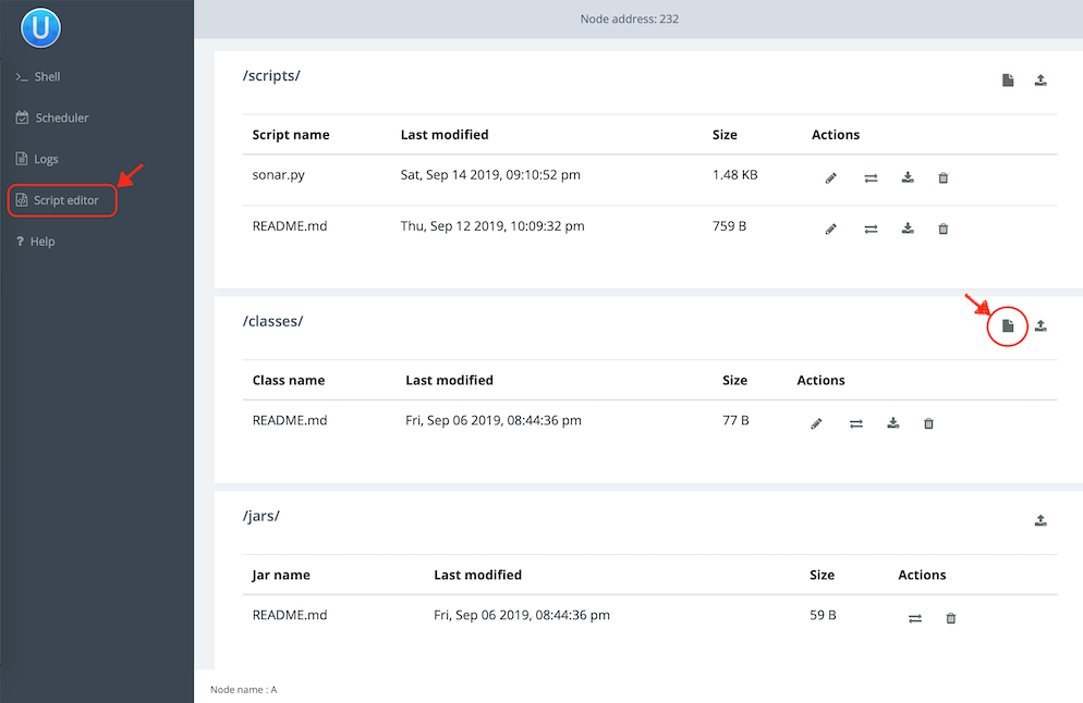
The same approach can be used to create Groovy scripts in the
scripts
folder.
Now start the 2-node network simulation that we have been using as a testbed, and on node B, load the agent:
> container.add 'echo', new EchoDaemon(); (1)
> ps
statemanager: org.arl.unet.state.StateManager - IDLE
remote: org.arl.unet.remote.RemoteControl - IDLE
rdp: org.arl.unet.net.RouteDiscoveryProtocol - IDLE
ranging: org.arl.unet.phy.Ranging - IDLE
uwlink: org.arl.unet.link.ECLink - IDLE
node: org.arl.unet.nodeinfo.NodeInfo - IDLE
websh: org.arl.fjage.shell.ShellAgent - RUNNING
simulator: org.arl.unet.sim.SimulationAgent - IDLE
phy: org.arl.unet.sim.HalfDuplexModem - IDLE
bbmon: org.arl.unet.bb.BasebandSignalMonitor - IDLE
arp: org.arl.unet.addr.AddressResolution - IDLE
transport: org.arl.unet.transport.SWTransport - IDLE
echo: EchoDaemon - IDLE (2)
router: org.arl.unet.net.Router - IDLE
mac: org.arl.unet.mac.CSMA - IDLE
WebGW-5c9c1c68385a388f: REMOTE| 1 |
Create an agent called
echo
based on the
EchoDaemon
class.
|
| 2 |
We see that the
echo
agent is now running.
|
Our daemon is up and running!
Once the daemon is successfully loaded on node B, we can test it from node A:
> subscribe phy (1)
> phy << new DatagramReq(to: host('B'), protocol: Protocol.USER, data: [42]) (2)
AGREE
phy >> TxFrameNtf:INFORM[type:DATA txTime:2809812247]
phy >> RxFrameStartNtf:INFORM[type:DATA rxTime:2811767943]
phy >> RxFrameNtf:INFORM[type:DATA from:31 to:232 rxTime:2811767943 (1 byte)]
> ntf.data
[42] (3)| 1 |
We subscribe to
phy
so that we can see the incoming echo response from the peer node.
|
| 2 | Transmit a physical layer frame containing the echo request and some data. |
| 3 | The data we sent was echoed back. |
We have written our first agent! Was easy, wasn’t it?
Unet modems also have a
classes
folder that accepts Groovy source files or compiled Java/Groovy class files. You can use the web interface of the modem to upload files to that folder. If your code has many class files, you may wish to package them together into a jar archive and place it in the
jars
folder.
|
28.3. Java echo daemon
If you’re a Java programmer and find the Groovy syntax daunting, you might prefer to write your agents in pure Java (at the expense of verbosity and more steps for testing). This is the equivalent Java code below for the Groovy agent we developed in the last section:
import org.arl.fjage.*;
import org.arl.unet.*;
public class EchoDaemon extends UnetAgent {
@Override
public void startup() {
// subscribe to all agents that provide the datagram service
subscribeForService(Services.DATAGRAM);
}
@Override
public void processMessage(Message msg) {
if (msg instanceof DatagramNtf && ((DatagramNtf)msg).getProtocol() == Protocol.USER) {
// we got an echo request!
// respond with a protocol DATA datagram
DatagramNtf ntf = (DatagramNtf)msg;
DatagramReq req = new DatagramReq(ntf.getSender());
req.setTo(ntf.getFrom());
req.setProtocol(Protocol.DATA);
req.setData(ntf.getData());
send(req);
}
}
}
In Java, you’ll first need to compile the Java code. Create a
EchoDaemon.java
file with the above contents. To compile it, you’ll need to have fjåge and unet-framework jar files on the classpath:
$ javac -cp lib/fjage-1.8.0.jar:lib/unet-framework-3.2.0.jar EchoDaemon.java
You should now have a
EchoDaemon.class
file which you copy to the
classes
folder. To avoid duplicate classes, remember to first delete the
EchoDaemon.groovy
file!
Finally, you can run the 2-node network simulator and test the agent, just as you did in the previous section.
28.4. Behaviors
Agents implement most of their functionality with behaviors.
| UnetStack is implemented on top of the fjåge agent framework. fjåge provides a set of standard behaviors for agents to extend. We will explore some of these behaviors in this section, but you are encouraged to read the fjåge documentation at your leisure to learn more. |
We have been implicitly using two behaviors so far. The
startup()
method is called by the
UnetAgent
base class using a
OneShotBehavior
, and the
processMessage()
method is called from a
MessageBehavior
. While you could have manually added these behaviors, the
UnetAgent
base class does this for you, because almost all Unet agents require this.
Let’s next look at a use case for explicitly adding other behaviors. Say we wanted our echo daemon to not respond immediately, but after 7 seconds. How would we do that?
We could of course add a
delay(7000)
in the
processMessage()
method, but that would be a bad idea. If we did that, the agent would sleep for 7 seconds on receiving a request and not process any request from any other nodes! We want the agent to be responsive while waiting, and so do not want to block execution. Instead, we want a behavior that will occur 7 seconds later — this is precisely what a
WakerBehavior
does. Here’s our new
processMessage()
method:
@Override
void processMessage(Message msg) {
if (msg instanceof DatagramNtf && msg.protocol == Protocol.USER) {
// respond to protocol USER datagram with protocol DATA datagram after 7 seconds
add new WakerBehavior(7000, {
send new DatagramReq(
recipient: msg.sender,
to: msg.from,
protocol: Protocol.DATA,
data: msg.data
)
})
}
}
The
WakerBehavior
that we add is triggered 7000 ms later, and the echo response is sent in that behavior. Simple!
Behaviors in Groovy use closures to make the syntax easy to work with. If you were writing your agent in Java, you’d need to create an anonymous class and override the
onWake()
method.
|
Go ahead and replace the
processMessage()
method in your
EchoDaemon.groovy
file and try it! In order to reload the agent, all you need to do on node B is:
> container.kill echo
true
> container.add 'echo', new EchoDaemon();And now you can send an echo request from node A as before and see that the response is delayed by 7 seconds.
You could also send a second request during those 7 seconds, and the echo daemon on node B would process that concurrently. You can send 2 echo requests right after each other, and you’ll see the corresponding echo responses 7 seconds later, but right after each other.
28.5. Parameters
We have seen many agents with parameters that you can get/set. If we wanted to make our echo daemon delay configurable, it would be perfect to expose it as a parameter. Let’s do that next.
With the echo daemon loaded on node B, we see that it doesn’t have any configurable parameters by default:
> echo
<<< EchoDaemon >>>
Let’s add a title, description and one
delay
parameter to our daemon:
import org.arl.fjage.*
import org.arl.fjage.param.Parameter
import org.arl.unet.*
class EchoDaemon extends UnetAgent {
enum Params implements Parameter { (1)
delay
}
final String title = 'Echo Daemon' (2)
final String description = 'Echoes any USER datagrams back as DATA' (3)
int delay = 7000 (4)
@Override
void startup() {
// subscribe to all agents that provide the datagram service
subscribeForService(Services.DATAGRAM)
}
@Override
void processMessage(Message msg) {
if (msg instanceof DatagramNtf && msg.protocol == Protocol.USER) {
// respond to protocol USER datagram with protocol DATA datagram after 7 seconds
add new WakerBehavior(delay, {
send new DatagramReq(
recipient: msg.sender,
to: msg.from,
protocol: Protocol.DATA,
data: msg.data
)
})
}
}
List<Parameter> getParameterList() { (5)
allOf(Params)
}
}| 1 | Declare a list of parameters that the agent advertises. We have declared this enum as an inner class, but you could choose to declare it as a separate class if you wish. |
| 2 | Provide a descriptive title for the agent. |
| 3 | Provide a descriptive text for the agent. |
| 4 | Declare the parameter. |
| 5 | Advertise the list of parameters. |
| Note that we had to take 3 steps to add a parameter: declare a list of parameters, declare the parameter, and advertise the parameter. While this might seem like a lot, bear in mind that parameters are much more than just an agent’s class attributes. Parameters can be get/set remotely, even from a different Java VM, different computer, or through a UnetSocket gateway API. |
If you were writing the agent in Java instead of Groovy, you’d need to implement getters and setters for parameter
delay
, rather than simply declare the attribute. This is because Groovy automatically creates the getters and setters for you.
|
Let’s see how the agent looks with parameters. Reload the agent on node B and check its parameters:
> container.kill agent('echo')
true
> container.add 'echo', new EchoDaemon();
> echo
<<< Echo Daemon >>> (1)
Echoes any USER datagrams back as DATA (2)
[EchoDaemon.Params]
delay = 7000
> echo.delay
7000
> echo.delay = 5000
5000
> echo.delay
5000| 1 | Notice the change in title. |
| 2 | The description is shown here. |
We have changed the delay from 7 seconds to 5 seconds. Go ahead and send a echo request from node A and see that you get a response back in 5 seconds!
If you want to compute parameter values on demand or validate parameters, you can implement getters/setters for the parameter, and they will be called. If you want a read-only parameter, you can declare the attribute as
private
and implement only a getter for that parameter.
|
While our example above uses a static description, the description can also be dynamic. This can be useful if you want to display agent’s status information in the description. To implement dynamic descriptions, simply replace the
description
attribute by a getter
getDescription()
that returns a
String
description when called.
|
28.6. Services, capabilities, and notifications
Most of the agents we have been interacting with, have advertised services, and sometimes, optional capabilities. They also honor requests and publish unsolicited notifications. All of these are quite straightforward to implement, and you can explore some of these features in this blog article on how to implement a simple PHYSICAL service agent (modem driver). We will explore some of these in the next chapter, along with other cool features like finite state machine behaviors and protocol data unit (PDU) codecs.
29. Implementing network protocols
You now know how to write simple agents. But real world network protocols demand more complexity such as advertising services, looking up other agents, providing parameters that are computed on demand, encoding/decoding complex PDUs, generating random variates, and describing behaviors as finite state machines (FSMs). In this chapter, we illustrate how to do all these things with ease, using a few examples.
In
Chapter 20
, we looked at the MAC service in detail. In the next few sections, we develop three simple MAC agents (
MySimplestMac
,
MySimpleThrottledMac
and
MySimpleHandshakeMac
) to illustrate how network protocols and services are implemented by agents. The MAC agents are intentionally kept simple and not optimized for performance, as we wish to illustrate the key aspects of MAC agent development without getting lost in the details of optimal protocols.
29.1. Simple MAC without handshake
To illustrate how a MAC agent might work, let us start with a simple MAC agent that grants every reservation request as soon as it is made:
import org.arl.fjage.*
import org.arl.unet.*
import org.arl.unet.mac.*
class MySimplestMac extends UnetAgent {
@Override
void setup() {
register Services.MAC // advertise that the agent provides a MAC service
}
@Override
Message processRequest(Message msg) {
if (msg instanceof ReservationReq) {
// check requested duration
if (msg.duration <= 0) return new RefuseRsp(msg, 'Bad reservation duration')
// prepare START reservation notification
ReservationStatusNtf ntf1 = new ReservationStatusNtf(
recipient: msg.sender,
inReplyTo: msg.msgID,
to: msg.to,
status: ReservationStatus.START)
// prepare END reservation notification
ReservationStatusNtf ntf2 = new ReservationStatusNtf(
recipient: msg.sender,
inReplyTo: msg.msgID,
to: msg.to,
status: ReservationStatus.END)
// send START reservation notification immediately
add new OneShotBehavior({
send ntf1
})
// wait for reservation duration, and then send END reservation notification
add new WakerBehavior(Math.round(1000*msg.duration), {
send ntf2
})
// return a reservation response, which defaults to an AGREE performative
return new ReservationRsp(msg)
}
return null
}
}Note a number of interesting features of the code above:
-
The
setup()method is used to advertise the service provided by this agent. -
We provide basic error checking, and refuse a request that is invalid, providing a descriptive reason.
-
We prepare the AGREE response as well as the START and END status notification messages, all at once. We send out the START notification immediately (using a
OneShotBehavior), use aWakerBehaviorto schedule the END notification to be sent out at an appropriate time, and then simply return the AGREE response. The use of theOneShotBehaviorensures that the START notification is sent after the AGREE response, and not before. -
We return a
nullif we don’t understand the request, allowing the superclass to respond with a NOT_UNDERSTOOD message.
While the above code implements a fully functional MAC agent, it needs to respond to
ReservationCancelReq
,
ReservationAcceptReq
and
TxAckReq
messages, and provide
channelBusy
,
reservationPayloadSize
,
ackPayloadSize
,
maxReservationDuration
and
recommendedReservationDuration
parameters in order to comply with the MAC service specification (
Chapter 20
). We add this functionality trivially, by responding to the messages with
RefuseRsp
(message with a
REFUSE
performative and a descriptive reason), and returning default values for all the parameters. The resulting complete source code is shown below:
import org.arl.fjage.*
import org.arl.fjage.param.Parameter
import org.arl.unet.*
import org.arl.unet.mac.*
class MySimplestMac extends UnetAgent {
@Override
void setup() {
register Services.MAC
}
@Override
Message processRequest(Message msg) {
switch (msg) {
case ReservationReq:
if (msg.duration <= 0) return new RefuseRsp(msg, 'Bad reservation duration')
ReservationStatusNtf ntf1 = new ReservationStatusNtf(
recipient: msg.sender,
inReplyTo: msg.msgID,
to: msg.to,
status: ReservationStatus.START)
ReservationStatusNtf ntf2 = new ReservationStatusNtf(
recipient: msg.sender,
inReplyTo: msg.msgID,
to: msg.to,
status: ReservationStatus.END)
add new OneShotBehavior({
send ntf1
})
add new WakerBehavior(Math.round(1000*msg.duration), {
send ntf2
})
return new ReservationRsp(msg)
case ReservationCancelReq:
case ReservationAcceptReq: // respond to other requests defined
case TxAckReq: // by the MAC service with a RefuseRsp
return new RefuseRsp(msg, 'Not supported')
}
return null
}
// expose parameters defined by the MAC service, with just default values
@Override
List<Parameter> getParameterList() {
return allOf(MacParam) // advertise the list of parameters
}
final boolean channelBusy = false // parameters are marked as 'final'
final int reservationPayloadSize = 0 // to ensure that they are read-only
final int ackPayloadSize = 0
final float maxReservationDuration = Float.POSITIVE_INFINITY
final Float recommendedReservationDuration = null
}Now we have a fully-compliant, but very simple, MAC agent!
29.2. Testing our simple MAC
The
MySimplestMac
agent from the previous section is available in the
samples
folder of your Unet simulator. To test it, fire up the 2-node network simulator and connect to node A:
> ps
remote: org.arl.unet.remote.RemoteControl - IDLE
state: org.arl.unet.state.StateManager - IDLE
rdp: org.arl.unet.net.RouteDiscoveryProtocol - IDLE
ranging: org.arl.unet.phy.Ranging - IDLE
uwlink: org.arl.unet.link.ECLink - IDLE
node: org.arl.unet.nodeinfo.NodeInfo - IDLE
websh: org.arl.fjage.shell.ShellAgent - RUNNING
simulator: org.arl.unet.sim.SimulationAgent - IDLE
phy: org.arl.unet.sim.HalfDuplexModem - IDLE
bbmon: org.arl.unet.bb.BasebandSignalMonitor - IDLE
arp: org.arl.unet.addr.AddressResolution - IDLE
transport: org.arl.unet.transport.SWTransport - IDLE
router: org.arl.unet.net.Router - IDLE
mac: org.arl.unet.mac.CSMA - IDLE
We see that the
org.arl.unet.mac.CSMA
agent is the current
mac
. To use our
MySimplestMac
agent, you first need to kill the
org.arl.unet.mac.CSMA
agent, and then load the
MySimplestMac
agent:
> container.kill mac
true
> container.add 'mac', new MySimplestMac()
mac
> ps
remote: org.arl.unet.remote.RemoteControl - IDLE
state: org.arl.unet.state.StateManager - IDLE
rdp: org.arl.unet.net.RouteDiscoveryProtocol - IDLE
ranging: org.arl.unet.phy.Ranging - IDLE
uwlink: org.arl.unet.link.ECLink - IDLE
node: org.arl.unet.nodeinfo.NodeInfo - IDLE
websh: org.arl.fjage.shell.ShellAgent - RUNNING
simulator: org.arl.unet.sim.SimulationAgent - IDLE
phy: org.arl.unet.sim.HalfDuplexModem - IDLE
bbmon: org.arl.unet.bb.BasebandSignalMonitor - IDLE
arp: org.arl.unet.addr.AddressResolution - IDLE
transport: org.arl.unet.transport.SWTransport - IDLE
router: org.arl.unet.net.Router - IDLE
mac: MySimplestMac - IDLE
> mac
« MySimplestMac »
[org.arl.unet.mac.MacParam]
ackPayloadSize ⤇ 0
channelBusy ⤇ false
maxReservationDuration ⤇ Infinity
recommendedReservationDuration ⤇ null
reservationPayloadSize ⤇ 0It’s loaded and working!
Now, you can ask for a reservation and see if it responds correctly:
> mac << new ReservationReq(to: 31, duration: 3.seconds)
ReservationRsp:AGREE
mac >> ReservationStatusNtf:INFORM[to:31 status:START]
mac >> ReservationStatusNtf:INFORM[to:31 status:END]Indeed it does! The START notification arrives immediately after the AGREE response, and the END notification arrives about 3 seconds later.
29.3. Simple MAC with throttling
While the above simple MAC would work well when the traffic offered to it is random, it will perform poorly if the network is fully loaded. All nodes would constantly try to access the channel, collide and the throughput would plummet. To address this concern, one may add an exponentially distributed random backoff (Poisson arrival to match the assumption of Aloha) for every request, to introduce randomness. The backoff could be chosen to offer a normalized network load of approximately 0.5, since this generates the highest throughput for Aloha.
Here’s the updated code with some bells and whistles:
import org.arl.fjage.*
import org.arl.fjage.param.Parameter
import org.arl.unet.*
import org.arl.unet.phy.*
import org.arl.unet.mac.*
class MySimpleThrottledMac extends UnetAgent {
private final static double TARGET_LOAD = 0.5
private final static int MAX_QUEUE_LEN = 16
(1)
private AgentID phy
boolean busy = false // is a reservation currently ongoing?
Long t0 = null // time of last reservation start, or null
Long t1 = null // time of last reservation end, or null
int waiting = 0
@Override
void setup() {
register Services.MAC
}
@Override
void startup() {
phy = agentForService(Services.PHYSICAL) (2)
}
@Override
Message processRequest(Message msg) {
switch (msg) {
case ReservationReq:
if (msg.duration <= 0) return new RefuseRsp(msg, 'Bad reservation duration')
if (waiting >= MAX_QUEUE_LEN) return new RefuseRsp(msg, 'Queue full')
ReservationStatusNtf ntf1 = new ReservationStatusNtf(
recipient: msg.sender,
inReplyTo: msg.msgID,
to: msg.to,
status: ReservationStatus.START)
ReservationStatusNtf ntf2 = new ReservationStatusNtf(
recipient: msg.sender,
inReplyTo: msg.msgID,
to: msg.to,
status: ReservationStatus.END)
// grant the request after a random backoff (3)
AgentLocalRandom rnd = AgentLocalRandom.current() (4)
double backoff = rnd.nextExp(TARGET_LOAD/msg.duration/nodes) (5)
long t = currentTimeMillis()
if (t0 == null || t0 < t) t0 = t
t0 += Math.round(1000*backoff) // schedule packet with a random backoff
if (t0 < t1) t0 = t1 // after the last scheduled packet (6)
long duration = Math.round(1000*msg.duration)
t1 = t0 + duration
waiting++
add new WakerBehavior(t0-t, { (7)
send ntf1
busy = true
waiting--
add new WakerBehavior(duration, {
send ntf2
busy = false
})
})
return new ReservationRsp(msg)
case ReservationCancelReq:
case ReservationAcceptReq:
case TxAckReq:
return new RefuseRsp(msg, 'Not supported')
}
return null
}
// expose parameters defined by the MAC service, and one additional parameter
@Override
List<Parameter> getParameterList() {
return allOf(MacParam, Param)
}
enum Param implements Parameter {
nodes (8)
}
int nodes = 6 // number of nodes in network, to be set by user
final int reservationPayloadSize = 0
final int ackPayloadSize = 0
final float maxReservationDuration = Float.POSITIVE_INFINITY
boolean getChannelBusy() { (9)
return busy
}
float getRecommendedReservationDuration() { (10)
return get(phy, Physical.DATA, PhysicalChannelParam.frameDuration)
}
}| 1 | We define a few attributes to keep track of channel state and reservation queue. |
| 2 |
We lookup other agents in
startup()
after they have had a chance to advertise their services during the setup phase.
|
| 3 | Requests are no longer granted immediately, but after a random backoff instead. |
| 4 |
Random numbers are generated using a
AgentLocalRandom
utility. This utility ensures repeatable results during discrete event simulation, aiding with debugging, and so is the preferred way of generating random variates.
|
| 5 |
The
nextExp()
function generate a exponentially distributed random number with a specified rate parameter. The rate parameter is computed such that the average backoff introduced helps to achieve the specified target load.
|
| 6 |
In Groovy, a comparison with
null
(initial value of
t1
) is permitted, and will always be false.
|
| 7 | Note that we no longer send the START notification immediately. Instead we schedule it after a backoff, and then schedule the END notification after the reservation duration from the START. |
| 8 |
We implement one user configurable parameter
nodes
, and advertise it.
|
| 9 |
Parameter
busy
is no longer always false, since we now keep track of reservations. We return
busy
to be true only during the time between a reservation START and END.
|
| 10 |
Parameter
recommendedReservationDuration
is now determined based on the frame duration of the PHYSICAL service, assuming that most reservations are for transmitting one frame. A client is free to choose a longer reservation time, if it wishes to transmit many frames in one go (as it should for efficient use of the channel).
|
A copy of this code is available in the
samples
folder of your Unet simulator. We encourage you to test it out, in the same way as we tested
MySimplestMac
in
Section 29.2
. You’ll find that the START notification no longer arrives immediately after the AGREE response, but arrives a few seconds later, after a random backoff.
29.4. Simple MAC with handshake
While the MAC agents we have developed so far are fully functional, they are simple, and do not involve any signaling for channel reservation. Many MAC protocols such as MACA and FAMA involve a handshake using RTS and CTS PDUs. To illustrate how more complex protocols are developed using UnetStack, we implement a simple RTS-CTS 2-way handshake-based MAC agent next.
Many communication protocols are best described using an FSM. We illustrate the FSM for our simple handshake-based MAC agent in Figure 10 .
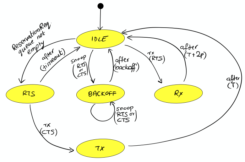
When the channel is free, the agent is in an IDLE state. If the agent receives a
ReservationReq
, it switches to the RTS state and sends an RTS PDU to the intended destination node. If it receives a CTS PDU back, then it switches to a TX state and urges the client to transmit data via a
ReservationStatusNtf
with a START status. After the reservation period is over, the agent switches back to the IDLE state. If no CTS PDU is received in the RTS state for a while, the agent times out and returns to the IDLE state after informing the client of a reservation FAILURE.
If the agent receives an RTS PDU in the IDLE state, it switches to the RX state and responds with a CTS PDU. The node initiating the handshake may then transmit data for the reservation duration. After the duration (plus some allowance for 2-way propagation delay), the agent switches back to the IDLE state. If the agent overhears (aka snoops) RTS or CTS PDUs destined for other nodes, it switches to a BACKOFF state for a while. During the state, it does not initiate or respond to RTS PDUs. After the backoff period, it switches back to the IDLE state.
Our RTS and CTS PDUs are identified by a protocol number. Since we are implementing a MAC protocol, we choose to tag our PDUs using the protocol number reserved for MAC agents (
Protocol.MAC
). We also define some timeouts and delays that we will need to use:
int PROTOCOL = Protocol.MAC
float RTS_BACKOFF = 2.seconds
float CTS_TIMEOUT = 5.seconds
float BACKOFF_RANDOM = 5.seconds
float MAX_PROP_DELAY = 2.seconds
Communication protocols often use complicated PDU formats. UnetStack provides a
PDU
class to help encode/decode PDUs. Although the RTS and CTS PDUs have a pretty simple format, the PDU is still useful in defining the format clearly:
int RTS_PDU = 0x01
int CTS_PDU = 0x02
PDU pdu = PDU.withFormat {
uint8('type') // RTS_PDU/CTS_PDU
uint16('duration') // ms
}
Here we have defined a PDU with two fields — type (8 bit) and duration (16 bit). The type may be either of RTS_PDU or CTS_PDU, while the duration will specify the reservation duration in milliseconds. We will later use this
pdu
object to encode and decode these PDUs.
Now comes the heart of our MAC protocol implementation –- the FSM shown in Figure 10 . First we define the FSM states and the events that the FSM reacts to:
enum State {
IDLE, RTS, TX, RX, BACKOFF
}
enum Event {
RX_RTS, RX_CTS, SNOOP_RTS, SNOOP_CTS
}
Next we use the
FSMBuilder
utility class to construct a
FSMBehavior
from a declarative concise representation of the FSM.
The FSM states are defined using the
state(…)
declarations. The actions to take when entering/exiting a state are defined in the
onEnter
/
onExit
clauses. The behavior of the FSM in response to events are defined using the
onEvent(…)
clauses. Timers that operate in a state are defined using the
after(…)
clauses. Finally actions to take continuously while in a state are defined using the
action
clause.
It should be easy to see the direct mapping between the FSM diagram and the FSM code below:
int MAX_RETRY = 3
int MAX_QUEUE_LEN = 16
Queue<ReservationReq> queue = new ArrayDeque<ReservationReq>(MAX_QUEUE_LEN)
FSMBehavior fsm = FSMBuilder.build {
int retryCount = 0
float backoff = 0
def rxInfo
def rnd = AgentLocalRandom.current()
state(State.IDLE) {
action {
if (!queue.isEmpty()) {
// add random backoff for each reservation to allow other nodes
// a chance to reserve, especially in case of a heavily loaded network
after(rnd.nextDouble(0, BACKOFF_RANDOM)) {
setNextState(State.RTS)
}
}
block()
}
onEvent(Event.RX_RTS) { info ->
rxInfo = info
setNextState(State.RX)
}
onEvent(Event.SNOOP_RTS) {
backoff = RTS_BACKOFF
setNextState(State.BACKOFF)
}
onEvent(Event.SNOOP_CTS) { info ->
backoff = info.duration + 2*MAX_PROP_DELAY
setNextState(State.BACKOFF)
}
}
state(State.RTS) {
onEnter {
Message msg = queue.peek()
def bytes = pdu.encode(
type: RTS_PDU,
duration: Math.ceil(msg.duration*1000))
phy << new TxFrameReq(
to: msg.to,
type: Physical.CONTROL,
protocol: PROTOCOL,
data: bytes)
after(CTS_TIMEOUT) {
if (++retryCount >= MAX_RETRY) {
sendReservationStatusNtf(queue.poll(), ReservationStatus.FAILURE)
retryCount = 0
}
setNextState(State.IDLE)
}
}
onEvent(Event.RX_CTS) {
setNextState(State.TX)
}
}
state(State.TX) {
onEnter {
ReservationReq msg = queue.poll()
retryCount = 0
sendReservationStatusNtf(msg, ReservationStatus.START)
after(msg.duration) {
sendReservationStatusNtf(msg, ReservationStatus.END)
setNextState(State.IDLE)
}
}
}
state(State.RX) {
onEnter {
def bytes = pdu.encode(
type: CTS_PDU,
duration: Math.round(rxInfo.duration*1000))
phy << new TxFrameReq(
to: rxInfo.from,
type: Physical.CONTROL,
protocol: PROTOCOL,
data: bytes)
after(rxInfo.duration + 2*MAX_PROP_DELAY) {
setNextState(State.IDLE)
}
rxInfo = null
}
}
state(State.BACKOFF) {
onEnter {
after(backoff) {
setNextState(State.IDLE)
}
}
onEvent(Event.SNOOP_RTS) {
backoff = RTS_BACKOFF
reenterState()
}
onEvent(Event.SNOOP_CTS) { info ->
backoff = info.duration + 2*MAX_PROP_DELAY
reenterState()
}
}
}
Do note that the above FSM includes a couple of details that were missing from the FSM diagram. Firstly, we implement a random backoff before switching to the RTS state to minimize contention. Secondly, we implement a
retryCount
counter to check the number of times a single
ReservationReq
has been tried. If it exceeds
MAX_RETRY
, we discard it. Thirdly, we have a
backoff
variable that allows different backoff times for different occasions. The variable is set each time, just before the state is changed to
State.BACKOFF
or before the backoff state is re-entered.
The FSM uses a simple utility method to send out
ReservationStatusNtf
notifications:
void sendReservationStatusNtf(ReservationReq msg, ReservationStatus status) {
send new ReservationStatusNtf(
recipient: msg.sender,
inReplyTo: msg.msgID,
to: msg.to,
from: addr,
status: status)
}
Now the hard work is done. We initialize our agent by registering the MAC service, looking up and subscribing to the PHYSICAL service (to transmit and receive PDUs), looking up our own address using the NODE_INFO service, and starting the
fsm
behavior:
AgentID phy
int addr
void setup() {
register Services.MAC
}
void startup() {
phy = agentForService(Services.PHYSICAL)
subscribe(phy)
subscribe(topic(phy, Physical.SNOOP))
add new OneShotBehavior({
def nodeInfo = agentForService(Services.NODE_INFO)
addr = get(nodeInfo, NodeInfoParam.address)
})
add(fsm)
}
Note that we subscribe to the
topic(phy, Physical.SNOOP)
in addition to
phy
. This allows us to snoop RTS/CTS PDUs destined for other nodes. Also note that the address lookup is performed in a
OneShotBehavior
to avoid having the agent to block while the node information agent is starting up.
Just like in the earlier MAC implementation, we have to respond to various requests defined by the MAC service specifications:
Message processRequest(Message msg) {
switch (msg) {
case ReservationReq:
if (msg.to == Address.BROADCAST || msg.to == addr)
return new RefuseRsp(msg, 'Reservation must have a destination node')
if (msg.duration <= 0 || msg.duration > maxReservationDuration)
return new RefuseRsp(msg, 'Bad reservation duration')
if (queue.size() >= MAX_QUEUE_LEN)
return new RefuseRsp(msg, 'Queue full')
queue.add(msg)
fsm.restart() // tell fsm to check queue, as it may block if empty
return new ReservationRsp(msg)
case ReservationCancelReq:
case ReservationAcceptReq:
case TxAckReq:
return new RefuseRsp(msg, 'Not supported')
}
return null
}
If we get a
ReservationReq
, we validate the attributes, add the request to our queue and return a
ReservationRsp
. For other requests that we do not support, we simply refuse them.
If we receive PDUs from the physical agent, they come as
RxFrameNtf
messages via the
processMessage()
method. For all PDUs with a protocol number that we use, we decode them. We trigger appropriate FSM events in response to RTS and CTS PDUs -– RX_RTS and RX_CTS events for PDUs destined to us, and SNOOP_RTS and SNOOP_CTS events for PDUs that we overhear:
void processMessage(Message msg) {
if (msg instanceof RxFrameNtf && msg.protocol == PROTOCOL) {
def rx = pdu.decode(msg.data)
def info = [from: msg.from, to: msg.to, duration: rx.duration/1000.0]
if (rx.type == RTS_PDU)
fsm.trigger(info.to == addr ? Event.RX_RTS : Event.SNOOP_RTS, info)
else if (rx.type == CTS_PDU)
fsm.trigger(info.to == addr ? Event.RX_CTS : Event.SNOOP_CTS, info)
}
}Finally, we expose the parameters required by the MAC service specification:
List<Parameter> getParameterList() { // publish list of all exposed parameters
return allOf(MacParam)
}
final int reservationPayloadSize = 0 // read-only
final int ackPayloadSize = 0 // read-only
final float maxReservationDuration = 65.535 // read-only
boolean getChannelBusy() { // considered busy if fsm is not IDLE
return fsm.currentState.name != State.IDLE
}
float getRecommendedReservationDuration() { // recommended duration: one DATA packet
return get(phy, Physical.DATA, PhysicalChannelParam.frameDuration)
}
We are done! You can find the full listing of the
MySimpleHandshakeMac
agent in
Appendix D
(and also in the
samples
folder of your Unet simulator).
29.5. Testing our simple MAC with handshake
Let’s try out this MAC. The steps are similar to
Section 29.2
, but since the handshake requires MAC to be running on all nodes, you will have to fire up the 2-node network and replace the default CSMA MAC with
MySimpleHandshakeMac
on both nodes (node A and node B):
> container.kill mac
true
> container.add 'mac', new MySimpleHandshakeMac();
> mac
« MySimpleHandshakeMac »
[org.arl.unet.mac.MacParam]
ackPayloadSize ⤇ 0
maxReservationDuration ⤇ 65.535
recommendedReservationDuration ⤇ 0.7
reservationPayloadSize ⤇ 0
Since the handshaking involves exchange of PDUs between nodes, it is instructive to see the PDUs being exchanged by subscribing to
phy
. You can make a reservation request on node A:
> subscribe phy
> mac << new ReservationReq(to: 31, duration: 3.seconds)
ReservationRsp:AGREE
phy >> TxFrameStartNtf:INFORM[type:CONTROL txTime:3631928985 txDuration:950]
phy >> RxFrameStartNtf:INFORM[type:CONTROL rxTime:3634151681]
phy >> RxFrameNtf:INFORM[type:CONTROL from:31 to:232 protocol:4 rxTime:3634151681 (3 bytes)]
mac >> ReservationStatusNtf:INFORM[to:31 from:232 status:START]
mac >> ReservationStatusNtf:INFORM[to:31 from:232 status:END]
We see that a CTS is transmitted (
TxFrameStartNtf
), then a RTS is received from node B (
RxFrameStartNtf
and
RxFrameNtf
). The reservation starts as soon as the CTS is received, and it ends 3 seconds later. Exactly as we wanted!
Part VI: Simulating underwater networks
30. Writing simulation scripts
We have been using simulations throughout the handbook, to demonstrate and test commands, scripts and agents without having to set up a real Unet. But how exactly do we tell the simulator what we want to simulate?
30.1. Integrated development environment
We have used the 2-node network simulation (
bin/unet samples/2-node-network.groovy
) umpteen times, but how did the simulator know where the nodes were and what agents were running on each node? That information must have been in the
2-node-network.groovy
simulation script, so let’s take a look at that script next.
While we could open the script in our favorite editor directly, let’s instead use the Unet IDE included with UnetStack, as it provides development tools that we will be needing in our journey. To start the Unet IDE:
$ bin/unet sim
Simulator IDE: http://localhost:8080/This should open the IDE in your default browser:
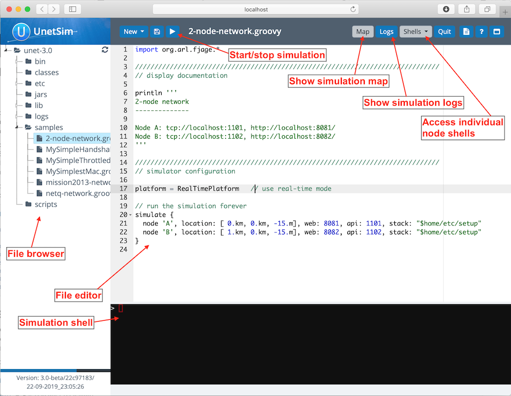
The IDE provides you with a fairly common 3-panel layout, with a file browser in the left panel, a simulation shell at the bottom, and a file editor occupying most of the window. At the top, you see several buttons. The key buttons to note are the
button that starts/stops simulations, the
Map
button that shows the current simulated nodes on a map, the 'Logs' button that allows you to view simulation logs, and a
Shells
dropdown that lists all the shells of simulated nodes. You can select any of the nodes from the list to connect to the shell of that node. The
Map
and
Shells
buttons are activated only once a simulation is running.
Load the
2-node-network.groovy
simulation script from the
samples
folder in the file editor. Then press
to run it.
You can either press the
button or type
sim.run 'samples/2-node-network.groovy'
to run the simulation from the simulation shell panel.
|
In the shell panel, you’ll see:
2-node network
--------------
Node A: tcp://localhost:1101, http://localhost:8081/
Node B: tcp://localhost:1102, http://localhost:8082/
To access node A shell, either control-click the URL for node A shell (displayed on the simulation shell) or select
Node A (232)
from the
Shells
dropdown menu. This will open the node A shell in a separate browser tab. Once you have access to the shells for your node, you are on familiar ground, as you have been working with numerous realtime simulations in previous chapters. Now, you can safely close the shell tab for now and go back to the IDE tab. The shell tab can be reopened anytime you want.
Next, try out the
Map
button, and you’ll see the 2 nodes in our simulation on a map:
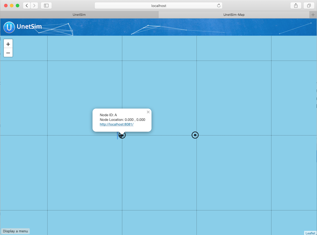
This map doesn’t look like much, with just 2 nodes 1 km apart on a blue background. The 2-node network simulation isn’t geolocated, so the map doesn’t have much to show. Let’s stop this simulation by pressing the
button, and start the
scripts/mission2013-network.groovy
simulation instead.
You can either press the
button or type
sim.stop
in the simulation shell panel to stop the currently running simulation.
|
Now open the
Map
, and you’ll get a much nicer map of the network deployed in southern Singapore waters:
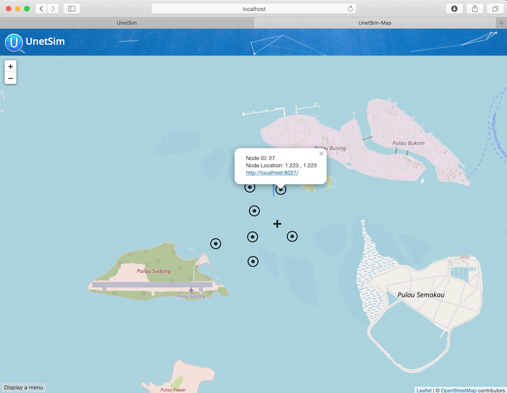
Clicking on each node shows some information about that node, and provides a link to opening that node’s shell (if it has a shell agent running). In case of mobile nodes ( Section 30.5 ), you’ll see the nodes moving on the map.
30.2. 2-node network
Now that we know how to use the IDE, let’s stop the mission2013 network simulation and reopen the 2-node network simulation in the file browser. Recall that we started off the previous section wanting to study the
2-node-network.groovy
simulation script in detail to see how it works. So let’s get down to it:
samples/2-node-network.groovy
:
import org.arl.fjage.* (1)
///////////////////////////////////////////////////////////////////////////////
// display documentation
println ''' (2)
2-node network
--------------
Node A: tcp://localhost:1101, http://localhost:8081/
Node B: tcp://localhost:1102, http://localhost:8082/
'''
///////////////////////////////////////////////////////////////////////////////
// simulator configuration
platform = RealTimePlatform (3)
// run the simulation forever
simulate { (4)
node 'A', location: [ 0.km, 0.km, -15.m], web: 8081, api: 1101, stack: "$home/etc/setup"
node 'B', location: [ 1.km, 0.km, -15.m], web: 8082, api: 1102, stack: "$home/etc/setup"
}| 1 | Import classes needed in the simulation script. |
| 2 | Display documentation. |
| 3 | Tell the simulator that we want to run in realtime mode. |
| 4 | Describe the simulation specifying nodes names 'A' and 'B', their locations, web interface port numbers, API port numbers and the default network stack to load on each node. |
The simulation script is very simple. All it does is specify that we want to use the
RealTimePlatform
(since we want to run a realtime simulation), and then define the two nodes in the simulation. Node attributes such as node name, location, ports, and stack (agents to load) are specified when describing each node.
Let’s next take a look at the
setup.groovy
script that describes the stack to load on each node:
etc/setup.groovy
:
import org.arl.fjage.Agent
boolean loadAgentByClass(String name, String clazz) { (1)
try {
container.add name, Class.forName(clazz).newInstance()
return true
} catch (Exception ex) {
return false
}
}
boolean loadAgentByClass(String name, String... clazzes) { (2)
for (String clazz: clazzes) {
if (loadAgentByClass(name, clazz)) return true
}
return false
}
loadAgentByClass 'arp', 'org.arl.unet.addr.AddressResolution'
loadAgentByClass 'ranging', 'org.arl.unet.phy.Ranging'
loadAgentByClass 'mac', 'org.arl.unet.mac.CSMA'
loadAgentByClass 'uwlink', 'org.arl.unet.link.ECLink', 'org.arl.unet.link.ReliableLink' (3)
loadAgentByClass 'transport', 'org.arl.unet.transport.SWTransport'
loadAgentByClass 'router', 'org.arl.unet.net.Router'
loadAgentByClass 'rdp', 'org.arl.unet.net.RouteDiscoveryProtocol'
loadAgentByClass 'state', 'org.arl.unet.state.StateManager'
container.add 'remote', new org.arl.unet.remote.RemoteControl(cwd: new File(home, 'scripts'), enable: false)
container.add 'bbmon', new org.arl.unet.bb.BasebandSignalMonitor(new File(home, 'logs/signals-0.txt').path, 64)| 1 | Helper function to load an agent given it’s class name. |
| 2 | Helper function to load an agent from a list of class names, picking the first available class. |
| 3 |
We use the second helper function to load
ECLink
if available (only premium stack), or
ReliableLink
as a fallback (available in basic stack).
|
While this script might look complicated, what it does is quite simple. It loads the standard agents in the network stack. The complicated bits in the script are mostly to handle errors, if certain agents are unavailable (e.g. agents from the premium stack). We could use a much simpler script to load the stack, if we wanted to avoid this complexity:
etc/setup.groovy
:
container.add 'arp', new org.arl.unet.addr.AddressResolution()
container.add 'ranging', new org.arl.unet.phy.Ranging()
container.add 'mac', new org.arl.unet.mac.CSMA()
container.add 'uwlink', new org.arl.unet.link.ReliableLink()
container.add 'transport', new org.arl.unet.transport.SWTransport()
container.add 'router', new org.arl.unet.net.Router()
container.add 'rdp', new org.arl.unet.net.RouteDiscoveryProtocol()
container.add 'state', new org.arl.unet.state.StateManager()
container.add 'remote', new org.arl.unet.remote.RemoteControl(cwd: new File(home, 'scripts'), enable: false)
container.add 'bbmon', new org.arl.unet.bb.BasebandSignalMonitor(new File(home, 'logs/signals-0.txt').path, 64)This script just loads all the standard agents in the basic stack.
If you wanted to customize the stack in the simulation, you could specify a different script to setup the stack, or provide a closure directly when defining the simulation:
simulate {
node 'A', location: [ 0.km, 0.km, -15.m], web: 8081, api: 1101, stack: "$home/scripts/custom.groovy"
node 'B', location: [ 1.km, 0.km, -15.m], web: 8082, api: 1102, stack: {
// only load 3 agents on node B
container.add 'arp', new org.arl.unet.addr.AddressResolution()
container.add 'mac', new org.arl.unet.mac.CSMA()
container.add 'uwlink', new org.arl.unet.link.ReliableLink()
}
}
Recall that in
Section 28.2
, we developed our own
EchoDaemon.groovy
agent. If we wanted to preload it in our 2-node network simulation, we can add
container.add 'echo', new EchoDaemon()
in the
custom.groovy
script or directly in the closure shown above.
|
30.3. Netiquette 3-node network
The
2-node-network.groovy
script defined 2 nodes that were 1 km apart, but were not geolocated. Recall from
Section 5.6
that specifying a node origin allows us to geolocate the nodes on a map. The
netq-network.groovy
simulation script does this:
samples/netq-network.groovy
:
import org.arl.fjage.RealTimePlatform
///////////////////////////////////////////////////////////////////////////////
// display documentation
println '''
Netiquette 3-node network
-------------------------
Node A: tcp://localhost:1101, http://localhost:8081/
Node B: tcp://localhost:1102, http://localhost:8082/
Node C: tcp://localhost:1103, http://localhost:8083/
'''
///////////////////////////////////////////////////////////////////////////////
// simulator configuration
platform = RealTimePlatform // use real-time mode
origin = [1.216, 103.851] (1)
simulate {
node 'A', location: [121.m, 137.m, -10.m], web: 8081, api: 1101, stack: "$home/etc/setup"
node 'B', location: [160.m, -232.m, -15.m], web: 8082, api: 1102, stack: "$home/etc/setup"
node 'C', location: [651.m, 140.m, -5.m], web: 8083, api: 1103, stack: "$home/etc/setup"
}| 1 |
The specified
origin
(latitude, longitude) applies to all nodes in the simulation.
|
Starting the simulation and opening the map shows the nodes on the map, since the origin allows the IDE to geolocate the nodes:
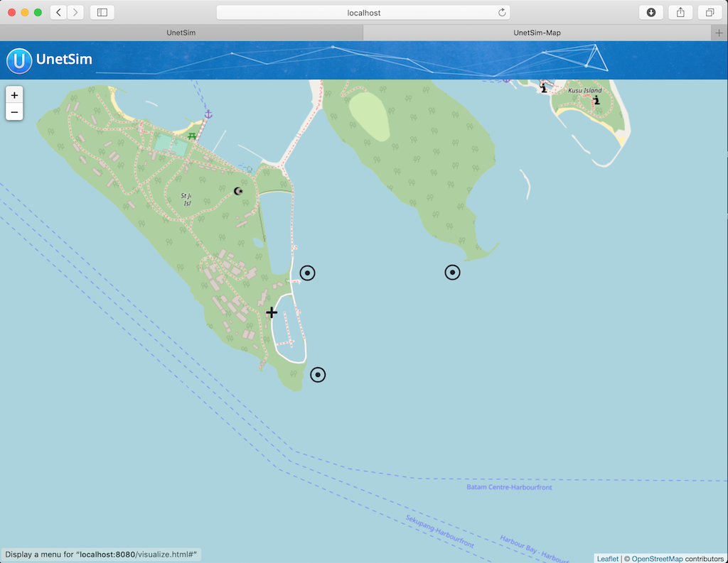
The
icon on the map marks the origin location.
30.4. Mission 2013 network
The simulation script is written in Groovy, so you can include complex logic in the script , if you wish. From this perspective, the
mission2013-network.groovy
script is instructive to look at:
samples/mission2013-network.groovy
:
import org.arl.fjage.RealTimePlatform
import org.arl.unet.sim.channels.Mission2013a
///////////////////////////////////////////////////////////////////////////////
// display documentation
println '''
MISSION 2013 network
--------------------
'''
Mission2013a.nodes.each { addr ->
println "Node $addr: tcp://localhost:${1100+addr}, http://localhost:${8000+addr}/"
}
///////////////////////////////////////////////////////////////////////////////
// simulator configuration
platform = RealTimePlatform // use real-time mode
channel = [ model: Mission2013a ] (1)
origin = [1.217, 103.743]
simulate {
Mission2013a.nodes.each { addr -> (2)
node "$addr", location: Mission2013a.nodeLocation[addr], web: 8000+addr, api: 1100+addr, stack: "$home/etc/setup"
}
}| 1 |
The
channel
property of the simulation enables us to define details of the simulated physical channel for the network. We will learn more about simulating channels in
Chapter 32
.
|
| 2 |
Nodes can be created programatically by iterating over the list of nodes defined in the
Mission2013a
class.
|
The
Mission2013a
class contains information about the MISSION 2013 experiment. The
mission2013-network.groovy
simulation script uses this information to create simulated nodes at the correct locations, and to define a channel model based on measurements during that experiment.
30.5. Node mobility
Nodes in a simulation may be mobile (e.g. autonomous underwater vehicles). Such nodes have motion models associated with them, to provide appropriate mobility during the simulation:
// AUV-1 moving in a straight line at constant speed
def n1 = node 'AUV-1', location: [0, 0, 0], mobility: true
n1.motionModel = [speed: 1.mps, heading: 30.deg]
// AUV-2 moving in a circle (constant speed, constant turn rate)
def n2 = node 'AUV-2', location: [0, 0, 0], mobility: true
n2.motionModel = [speed: 1.mps, turnRate: 1.dps]We can also define more complex motion models:
// AUV-3 moving in a lawnmower pattern
def n3 = node 'AUV-3', location: [-20.m, -150.m, 0], heading: 0.deg, mobility: true
n3.motionModel = MotionModel.lawnmower(speed: 1.mps, leg: 200.m, spacing: 20.m, legs: 10)
// AUV-4 moving as defined below, using time or duration
def n4 = node 'AUV-4', location: [-50.m, -50.m, 0], mobility: true
n4.motionModel = [
[time: 0.minutes, heading: 60.deg, speed: 1.mps],
[time: 3.minutes, turnRate: 2.dps, diveRate: 0.1.mps],
[time: 4.minutes, turnRate: 0.dps, diveRate: 0.mps],
[time: 7.minutes, turnRate: 2.dps ],
[time: 8.minutes, turnRate: 0.dps ],
[duration: 3.minutes, turnRate: 2.dps, diveRate: -0.1.mps],
[duration: 1.minute, turnRate: 0.dps, diveRate: 0.mps]
]We can even combine motion models:
def n5 = node 'AUV-5', location: [-20.m, -150.m, 0], heading: 0.deg, mobility: true
// dive to 30m before starting survey
n5.motionModel = [
[duration: 5.minutes, speed: 1.mps, diveRate: 0.1.mps],
[diveRate: 0.mps]
]
// then do a lawnmower survey
n5.motionModel += MotionModel.lawnmower(speed: 1.mps, leg: 200.m, spacing: 20.m, legs: 10)
// finally, come back to the surface and stop
n5.motionModel += [
[duration: 5.minutes, speed: 1.mps, diveRate: -0.1.mps],
[diveRate: 0.mps, speed: 0.mps]
]Let’s put AUVs 1-4 together into a single simulation script:
auv-network.groovy
import org.arl.fjage.RealTimePlatform
import org.arl.unet.sim.MotionModel
platform = RealTimePlatform
simulate {
def n1 = node 'AUV-1', location: [0, 0, 0], mobility: true
n1.motionModel = [speed: 1.mps, heading: 30.deg]
def n2 = node 'AUV-2', location: [0, 0, 0], mobility: true
n2.motionModel = [speed: 1.mps, turnRate: 1.dps]
def n3 = node 'AUV-3', location: [-20.m, -150.m, 0], heading: 0.deg, mobility: true
n3.motionModel = MotionModel.lawnmower(speed: 1.mps, leg: 200.m, spacing: 20.m, legs: 10)
def n4 = node 'AUV-4', location: [-50.m, -50.m, 0], mobility: true
n4.motionModel = [
[time: 0.minutes, heading: 60.deg, speed: 1.mps],
[time: 3.minutes, turnRate: 2.dps, diveRate: 0.1.mps],
[time: 4.minutes, turnRate: 0.dps, diveRate: 0.mps],
[time: 7.minutes, turnRate: 2.dps ],
[time: 8.minutes, turnRate: 0.dps ],
[duration: 3.minutes, turnRate: 2.dps, diveRate: -0.1.mps],
[duration: 1.minute, turnRate: 0.dps, diveRate: 0.mps]
]
}
Save this
auv-network.groovy
in your
scripts
folder and run it. Open the map, and watch your AUV nodes move!
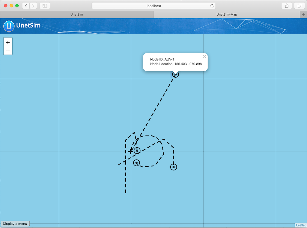
31. Discrete event simulation
Running simulations in realtime gives us an experience which is very similar to working with a real Unet, as we have seen in earlier chapters. This is very useful when you want to interact with the network manually, through a shell. However, as a network designer or protocol developer, you may sometimes need to run simulations to see how the network performs over days or months, and maybe run many such simulations, each with slightly different network settings or configuration. Doing this with a realtime simulator is impractical, as a realtime simulation would take days or months to run. The Unet simulator can be run in a discrete event mode, where the waiting time between events is fast-forwarded to yield results worth hours or days of real time within minutes. In this chapter, we explore how to use the disrete event mode for simulation of protocol performance.
31.1. ALOHA performance analysis
The hello world of the networking world is the ALOHA MAC protocol. The protocol is very simple: transmit a frame as soon as data arrives, without worrying about whether any other node is transmitting. While this behavior is straightforward to describe, simulating it accurately requires some thought.
Let’s say we want to simulate a network with ALOHA MAC. On each node, we expect data to arrive randomly, with a known average arrival rate. The total number of data "chunks" arriving per unit time across the network is termed as offered load . As soon as a data chunk arrives, the node transmits it to a randomly chosen destination node (other than itself). The number of successfully delivered data chunks per unit time, across the entire network, is called the throughput . We are interested to study how the throughput varies as a function of offered load.
ALOHA has been extensively studied in literature, and its theoretical performance is well known. In order to simulate a network that can be compared against theory, we need to ensure that our simulation matches the assumptions made in the theoretical derivations:
-
The random arrival process follows a Poisson distribution.
-
If two frames arrive at a receiver with some overlap in time, they collide and are lost. Neither frame can be successfully decoded.
-
Each node is half-duplex, i.e., it cannot receive a frame while it is transmitting.
-
No frames are lost due to noise or channel effects such as multipath.
-
There is no propagation delay between nodes.
Assumptions 2 and 4 together form a model called the protocol channel model. We tell the simulator to adopt this model:
channel.model = ProtocolChannelModel
Underwater acoustic modems are usually half-duplex, and the default modem model in the simulator is the
HalfDuplexModem
, so we shouldn’t need to do anything special for assumption 3. However, the
HalfDuplexModem
is smart enough to delay a transmission if another frame is being transmitted or received by the node, to avoid losing the other frame. While this is usually a good thing to do, it will violate assumption 3 and give us results that don’t agree with theory. To match the theoretical behavior, we have to stop any ongoing transmission or reception, when new data arrives for transmission:
phy << new ClearReq() // stop ongoing transmission/reception
phy << new TxFrameReq(to: dst, type: DATA) // transmit a data frame to dstThe offered load and throughput are usually normalized by the number of frames that can be supported by the channel per unit time. By setting the frame duration to be one second, we ensure that the normalization factor is 1 (one packet can be transitted per second without collision). To do this, we set up the simulated modem to have no header/preamble overheads, and exactly 1 second worth of data that it can carry in a frame:
modem.dataRate = [2400, 2400].bps // arbitrary data rate
modem.frameLength = [2400/8, 2400/8].bytes // 1 second worth of data per frame
modem.headerLength = 0 // no overhead from header
modem.preambleDuration = 0 // no overhead from preamble
modem.txDelay = 0 // don't simulate hardware delays
You can read more about
modem
models in
Section 32.1
.
|
A Poisson process (assumption 1) is easily simulated using the
PoissonBehavior
available in fjåge. Assumption 5 can also be easily met by placing all nodes at the same location.
Now let’s put a first version of our script together to simulate a 4-node ALOHA network:
import org.arl.fjage.*
import org.arl.unet.*
import org.arl.unet.phy.*
import org.arl.unet.sim.*
import org.arl.unet.sim.channels.*
channel.model = ProtocolChannelModel // use the protocol channel model
modem.dataRate = [2400, 2400].bps // arbitrary data rate
modem.frameLength = [2400/8, 2400/8].bytes // 1 second worth of data per frame
modem.headerLength = 0 // no overhead from header
modem.preambleDuration = 0 // no overhead from preamble
modem.txDelay = 0 // don't simulate hardware delays
def nodes = 1..4 // list with 4 nodes
def load = 0.2 // offered load to simulate
simulate 2.hours, { // simulate 2 hours of elapsed time
nodes.each { myAddr ->
def myNode = node "${myAddr}", address: myAddr, location: [0, 0, 0]
myNode.startup = { // startup script to run on each node
def phy = agentForService(Services.PHYSICAL)
def arrivalRate = load/nodes.size() // arrival rate per node
add new PoissonBehavior((long)(1000/arrivalRate), { // avg time between events in ms
def dst = rnditem(nodes-myAddr) // choose destination randomly (excluding self)
phy << new ClearReq()
phy << new TxFrameReq(to: dst, type: Physical.DATA)
})
}
}
}
// display collected statistics
println([trace.txCount, trace.rxCount, trace.offeredLoad, trace.throughput])
The script is easy to understand. In a 2-hour long simulation, we iterate over the list of nodes, and create each node at the origin. Each node adds a
PoissonBehavior
to generate random traffic at a rate corresponding to the offered
load
setting. The parameter of the Poisson behavior is the average time between events in milliseconds, which we compute based on the arrival rate. The destination for each transmission is randomly chosen from the list of nodes excluding the transmitting node. Once the simulation is completed, statistics are printed. The
trace
object is automatically defined by the simulator to collect typically required statistics.
The
rnditem(list)
function allows a random item to be chosen from a list. Other convenience functions related to random number generation include
rnd(min, max)
which generates a uniformly distributed random number between
min
and
max
, and
rndint(n)
which generates a uniformly distributed random number between
0
and
n-1
.
|
Open Unet IDE (
bin/unet sim
), create a new simulation script in the
scripts
folder, copy this code in, and run it. Within a few seconds, you should see the results:
[1459, 984, 0.2026, 0.1367]
1 simulation completed in 2.817 secondsSince this is a Monte-Carlo simulation driven by a random number generator, the statistics you see will be similar, but not identical. A total of 1459 frames were transmitted, and 984 of them were successfully received. The measured offered load was 0.2026, and the throughput was 0.1367.
Hang on a minute! The simulation was meant to run for 2 hours, but it finished in less than 3 seconds!!
That’s because we ran the simulation in a discrete event simulation mode (it is the default mode, if we don’t set
platform = RealTimePlatform
). We could have explicitly set it (
platform = DiscreteEventSimulator
), if we wanted. Now that we can run hours worth of simulations in seconds, we can go ahead and measure ALOHA throughput at various load settings:
import org.arl.fjage.*
import org.arl.unet.*
import org.arl.unet.phy.*
import org.arl.unet.sim.*
import org.arl.unet.sim.channels.*
println '''
Pure ALOHA simulation
=====================
TX Count\tRX Count\tOffered Load\tThroughput
--------\t--------\t------------\t----------'''
channel.model = ProtocolChannelModel // use the protocol channel model
modem.dataRate = [2400, 2400].bps // arbitrary data rate
modem.frameLength = [2400/8, 2400/8].bytes // 1 second worth of data per frame
modem.headerLength = 0 // no overhead from header
modem.preambleDuration = 0 // no overhead from preamble
modem.txDelay = 0 // don't simulate hardware delays
def nodes = 1..4 // list with 4 nodes
trace.warmup = 15.minutes // collect statistics after a while
for (def load = 0.1; load <= 1.5; load += 0.1) {
simulate 2.hours, { // simulate 2 hours of elapsed time
nodes.each { myAddr ->
def myNode = node "${myAddr}", address: myAddr, location: [0, 0, 0]
myNode.startup = { // startup script to run on each node
def phy = agentForService(Services.PHYSICAL)
def arrivalRate = load/nodes.size() // arrival rate per node
add new PoissonBehavior((long)(1000/arrivalRate), { // avg time between events in ms
def dst = rnditem(nodes-myAddr) // choose destination randomly (excluding self)
phy << new ClearReq()
phy << new TxFrameReq(to: dst, type: Physical.DATA)
})
}
}
} // simulate
// tabulate collected statistics
println sprintf('%6d\t\t%6d\t\t%7.3f\t\t%7.3f',
[trace.txCount, trace.rxCount, trace.offeredLoad, trace.throughput])
} // for
Other than the pretty printing to tabulate the output, you’ll see that we have added a
trace.warmup
time. This is to ensure that we only collect statistics after the simulation has reached steady state (in this case, after 15 minutes of simulation time).
A slightly beautified copy of the above code is available in the
samples/aloha.groovy
script. You can either run that, or run the above code. You should see something like this output:
Pure ALOHA simulation
=====================
TX Count RX Count Offered Load Throughput
-------- -------- ------------ ----------
614 525 0.068 0.058
1228 962 0.137 0.107
1871 1249 0.209 0.139
2480 1407 0.277 0.156
3093 1535 0.347 0.171
3759 1616 0.421 0.180
4273 1665 0.479 0.183
4971 1599 0.558 0.178
5540 1605 0.622 0.178
6256 1532 0.702 0.170
6940 1375 0.783 0.153
7338 1407 0.826 0.156
7992 1338 0.904 0.149
8598 1282 0.972 0.142
9394 1048 1.062 0.116
15 simulations completed in 102.494 seconds
As expected from the ALOHA protocol, the maximum throughput of about 0.18 is reached at an offered load of about 0.5. We plot this against the theoretical ALOHA performance curve (
y = x exp(-2x)
) in
Figure 16
.
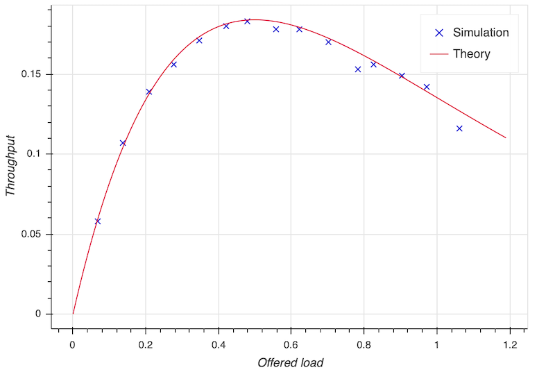
31.2. Logs, traces and statistics
When a simulation is run, usually two files are produced.
31.2.1. Log file
The
logs/log-0.txt
file contains detailed text logs from the Java logging framework. Your agents and simulation scripts may log additional information to this file using
log.info()
or
log.fine()
methods. This provides a flexible and customizable way to log events in your simulation for later analysis.
A typical extract of the log file is shown below:
1569242004546|INFO|org.arl.unet.nodeinfo.NodeInfo@558:setAddress|Node address changed to 1
1569242004548|INFO|Script1@558:invoke|Created static node 1 (1) @ [0, 0, 0]
1569242004552|INFO|org.arl.unet.nodeinfo.NodeInfo@558:setAddress|Node address changed to 2
1569242004553|INFO|Script1@558:invoke|Created static node 2 (2) @ [0, 0, 0]
1569242004553|INFO|org.arl.unet.nodeinfo.NodeInfo@558:setAddress|Node address changed to 3
1569242004554|INFO|Script1@558:invoke|Created static node 3 (3) @ [0, 0, 0]
1569242004554|INFO|org.arl.unet.nodeinfo.NodeInfo@558:setAddress|Node address changed to 4
1569242004554|INFO|Script1@558:invoke|Created static node 4 (4) @ [0, 0, 0]
1569242004555|INFO|Script1@558:invoke| --- BEGIN SIMULATION #1 ---
0|INFO|org.arl.unet.sim.SimulationContainer@558:init|Initializing agents...
0|INFO|org.arl.unet.sim.SimulationAgent/1@561:invoke|Loading simulator : SimulationAgent
0|INFO|org.arl.unet.nodeinfo.NodeInfo/1@560:init|Loading agent node v3.0
0|INFO|org.arl.unet.sim.HalfDuplexModem/1@559:init|Loading agent phy v3.0
:
:
5673|INFO|org.arl.unet.sim.SimulationAgent/4@570:call|TxFrameNtf:INFORM[type:DATA txTime:2066947222]
6511|INFO|org.arl.unet.sim.SimulationAgent/3@567:call|TxFrameNtf:INFORM[type:DATA txTime:1157370743]
10919|INFO|org.arl.unet.sim.SimulationAgent/4@570:call|TxFrameNtf:INFORM[type:DATA txTime:2072193222Note that the timestamp (first column) changes from the clock time to discrete event time when the simulation starts, and switches back to clock time when the simulation ends.
31.3. Trace files
31.4. JSON trace file
Since UnetStack 3.3.0, the default trace file is stored in a rich JSON format.
When running a simulation, a JSON trace file
logs/trace.json
is automatically generated. This file contains a detailed trace for every event in the network stack, on each node. You can even enable trace file generation on real modems and other Unet nodes (using
EventTracer.enable()
), and later combine the traces from multiple nodes to analyze network protocol operation and performance.
A small extract from a typical trace file is shown below:
{"version": "1.0","group":"EventTrace","events":[
{"group":"SIMULATION 1","events":[
{"time":1617877446718,"component":"arp::org.arl.unet.addr.AddressResolution/B","threadID":"0bfb305d-4920-4df0-af95-5282b048b5ec","stimulus":{"clazz":"org.arl.unet.addr.AddressAllocReq","messageID":"0bfb305d-4920-4df0-af95-5282b048b5ec","performative":"REQUEST","sender":"node","recipient":"arp"},"response":{"clazz":"org.arl.unet.addr.AddressAllocRsp","messageID":"3e421e28-89ca-44ec-bc65-16cc404d3703","performative":"INFORM","recipient":"node"}},
{"time":1617877446718,"component":"arp::org.arl.unet.addr.AddressResolution/A","threadID":"04f5b1b9-9178-4e27-aae7-e2a0c4ffcd89","stimulus":{"clazz":"org.arl.unet.addr.AddressAllocReq","messageID":"04f5b1b9-9178-4e27-aae7-e2a0c4ffcd89","performative":"REQUEST","sender":"node","recipient":"arp"},"response":{"clazz":"org.arl.unet.addr.AddressAllocRsp","messageID":"e0fe806d-625d-4261-b24c-6655b90cc06a","performative":"INFORM","recipient":"node"}},
:
:
]}
]}The trace is organized into a hierarchy of groups, each describing a simulation run or the execution of specific commands. A group consists of a sequence of events, with each event providing information on time of event, component (agent running on a node), thread ID, stimulus and response. The stimulus is typically a message received from another agent, and response a message sent to another agent. The thread ID ties multiple events, potentially across multiple agents and nodes, but with the same root cause together.
An experimental automated trace analysis tool can be used to produce sequence diagrams from JSON trace files.
Integrating the event tracing framework into your own agents is simple. All you need to do is to wrap messages that you generate in response to a stimulus with a
trace()
call. Some examples:
send trace(stimulus, new DatagramDeliveryNtf(stimulus))
request trace(stimulus, req), timeout31.5. Legacy trace file
The legacy trace file format is similar to the NS2 NAM trace. Since UnetStack 3.3.0, this format is no longer the default, but can be enabled easily in your simulation script if you need it:
trace.open(new File(home, 'logs/trace.nam'))The trace file contains information about all packet creation, transmission, reception and drop events. It also contains details of node motion. The tracer also computes basic statistics including queued packet count, transmitted packet count, received packet count, dropped packet count, offered load, actual load, average packet latency and normalized throughput. An extract from the trace file is shown below:
# BEGIN SIMULATION 1
n -t 8.005000 -s 3 -x 0.000000 -y 0.000000 -Z 0.000000 -a 3
+ -t 8.005000 -s 3 -d 2 -i 40839989 -p 0 -x {3.0 2.0 -1 ------- null}
- -t 8.005000 -s 3 -d 2 -i 40839989 -p 0 -x {3.0 2.0 -1 ------- null}
n -t 8.005000 -s 1 -x 0.000000 -y 0.000000 -Z 0.000000 -a 1
n -t 8.005000 -s 2 -x 0.000000 -y 0.000000 -Z 0.000000 -a 2
n -t 8.005000 -s 4 -x 0.000000 -y 0.000000 -Z 0.000000 -a 4
r -t 9.005000 -s 3 -d 2 -i 40839989 -p 0 -x {3.0 2.0 -1 ------- null}
r -t 9.005000 -s 3 -d 1 -i 40839989 -p 0 -x {3.0 2.0 -1 ------- null}
r -t 9.005000 -s 3 -d 4 -i 40839989 -p 0 -x {3.0 2.0 -1 ------- null}
+ -t 42.042000 -s 1 -d 2 -i 254433913 -p 0 -x {1.0 2.0 -1 ------- null}
- -t 42.042000 -s 1 -d 2 -i 254433913 -p 0 -x {1.0 2.0 -1 ------- null}
r -t 43.042000 -s 1 -d 2 -i 254433913 -p 0 -x {1.0 2.0 -1 ------- null}
r -t 43.042000 -s 1 -d 4 -i 254433913 -p 0 -x {1.0 2.0 -1 ------- null}
r -t 43.042000 -s 1 -d 3 -i 254433913 -p 0 -x {1.0 2.0 -1 ------- null}
:
:
d -t 584.925000 -s 1 -d 4 -i 259068939 -p 0 -x {1.0 4.0 -1 ------- null} -y CLEAR
+ -t 584.925000 -s 4 -d 1 -i -2069119004 -p 0 -x {4.0 1.0 -1 ------- null}
- -t 584.925000 -s 4 -d 1 -i -2069119004 -p 0 -x {4.0 1.0 -1 ------- null}
d -t 584.925000 -s 4 -d 1 -i -2069119004 -p 0 -x {4.0 1.0 -1 ------- null} -y COLLISION
d -t 584.925000 -s 4 -d 2 -i -2069119004 -p 0 -x {4.0 1.0 -1 ------- null} -y COLLISION
d -t 584.925000 -s 4 -d 3 -i -2069119004 -p 0 -x {4.0 1.0 -1 ------- null} -y COLLISION
d -t 585.747000 -s 1 -d 2 -i 259068939 -p 0 -x {1.0 4.0 -1 ------- null} -y BAD_FRAME
d -t 585.747000 -s 1 -d 3 -i 259068939 -p 0 -x {1.0 4.0 -1 ------- null} -y BAD_FRAME
:
:
# STATS: q=621, t=621, r=506, d=115, O=0.099, L=0.099, D=0.000, T=0.080
# END SIMULATION 1
Lines starting with
n
log node locations/motion. Lines starting with
+
denote packet arrival into the transmit queue. Lines starting with
-
log packet removal from the transmit queue, i.e., transmission. Lines starting with
r
denote packet reception (or overhearing). Lines starting with
d
log packet drops, and specify a reason for the drop.
CLEAR
indicates a packet transmission/reception abort due to a
ClearReq
request.
COLLISION
indicates that the packet was dropped because the node was busy receiving or transmitting another packet.
BAD_FRAME
indicates that the packet was corrupted (possibly due to interference from a colliding packet).
For more details on the trace file format, see NS2 NAM trace format .
| While the trace provides a simple file format and collects statistics for you, the events monitored by the legacy trace are currently limited to PHYSICAL service events. If you need to monitor or log events from other agents, you would want to use the JSON trace file. |
32. Modems and channel models
In Chapter 30 and Chapter 31 , we learned how to simulate Unets with many nodes, using a single computer. In fact, we have been using simulations throughout the handbook. In a simulated Unet, most agents are identical to the agents running in nodes on a real Unet. However, since the communication in a simulated Unet does not use a modem in water, we need a model for how a real modem behaves.
32.1. Modem models
A modem usually provides the PHYSICAL service (and optionally, the BASEBAND service). In a simulation, we need a simulated modem to provide these services with behaviors as close to reality as possible. The agent that models the modem behavior is called a
modem model
. The Unet simulator comes with the
HalfDuplexModem
model that can be customized to emulate various underwater acoustic modems.
Since the
HalfDuplexModem
is the default modem model, we don’t need to explicitly specify it. But if we wanted to, we could do it in the simulation script:
modem = [ model: org.arl.unet.sim.HalfDuplexModem ]| Some modem manufacturers may provide you with a modem model that more accurately matches the behaviors of their modem. This can be useful when simulating networks with modems from specific vendors. |
We can specify properties that control the behavior of the modem. You can either specify them while declaring the modem:
modem = [
model: org.arl.unet.sim.HalfDuplexModem,
dataRate: [800.bps, 2400.bps],
frameLength: [16.bytes, 64.bytes],
powerLevel: [0.dB, -10.dB],
preambleDuration: 5.ms
]or later, by assigning the properties individually:
modem.dataRate = [800.bps, 2400.bps]
modem.frameLength = [16.bytes, 64.bytes]
modem.powerLevel = [0.dB, -10.dB]
modem.preambleDuration = 5.ms
Indexed properties
dataRate
,
frameLength
,
maxFrameLength
,
janus
and
powerLevel
are specified as 3-tuples, with the first entry corresponding to the CONTROL channel, the second for the DATA channel, and the third for the JANUS frame type. If JANUS support is not required, the properties may be specified as 2-tuples.
If you run a realtime simulation with
modem.dataRate = [800.bps, 2400.bps]
, connect to a node’s shell, and then type in
phy[CONTROL].dataRate
, you may be surpirsed to see a much lower data rate (436 bps in this example). The 800 bps is the signaling rate, and exludes overheads from preamble and headers. The 436 bps is the effective average data rate across the frame, and includes all overheads.
|
Short descriptions and default values of these properties are shown below:
-
modem.dataRate = [256, 1024, 80] -
Communication link data rate (bps).
-
modem.frameLength = [24, 64, 8] -
Default frame length (bytes).
-
modem.maxFrameLength = [128, 512, 128] -
Maximum frame length (bytes)
-
modem.janus = [false, false, true] -
Support for JANUS frames.
-
modem.powerLevel = [-10, -10, -10] -
Transmit power level (dB re
refPowerLevel).
In addition to the above indexed properties, several other properties control the modem behavior:
-
modem.signalPowerLevel = -10 -
Transmit power level (dB re
refPowerLevel) for baseband signals. -
modem.preambleDuration = 0.2 -
Frame detection preamble duration (s).
-
modem.headerLength = 8 -
Frame header length (bytes).
-
modem.timestampLength = 6 -
Timestamp length (bytes), for timestamped frames.
-
modem.txDelay = 0.05 -
Transmission delay when switching from receive to transmit mode (s).
-
modem.timestampedTxDelay = 1.0 -
Transmission delay when scheduling transmission of a timestamped packet (s).
-
modem.maxPowerLevel = 0 -
Maximum allowable transmit power level (dB re
refPowerLevel). -
modem.minPowerLevel = -96 -
Minimum allowable transmit power level (dB re
refPowerLevel). -
modem.refPowerLevel = 185 -
Reference transmit power level (dB re µPa @ 1m).
-
modem.rxSensitivity = -200 -
Reference receive sensitivity (dB re µPa).
-
modem.carrierFrequency = 12000 -
Carrier frequency (Hz).
-
modem.basebandRate = 12000 -
Baseband sampling rate (samples/second).
-
modem.basebandRxDuration = 1.0 -
Baseband reception duration (s).
-
modem.maxSignalLength = 65536 -
Maximum allowable baseband signal length.
A modem model simulates the half-duplex nature of the modem, propagation delay, interference, packet detection and packet loss. In order to do this accurately, it uses a channel model.
32.2. Channel models
Channel models implement the
ChannelModel
interface. The default channel model is the
BasicAcousticChannel
, but can be reconfigured in the simulation script. Again, channel models can use either syntax:
channel = [
model: org.arl.unet.sim.channels.ProtocolChannelModel,
communicationRange: 3000.m,
pDetection: 0.9,
pDecoding: 0.8
]or
channel.model = org.arl.unet.sim.channels.ProtocolChannelModel
channel.communicationRange = 1000.m
channel.pDetection = 0.9
channel.pDecoding = 0.8The properties supported by a channel model depend on the specifics of that model. Let us next look at a few channel models that come with the Unet simulator.
32.2.1. Protocol channel model
The protocol channel model (
ProtocolChannelModel
) is the simplest of the channel models available in the Unet simulator. Although simple, it captures important first-order effects such as propagation delay, limited communication range, interference range, and collisions. It also captures the probabilistic nature of the channel. It therefore serves as a good first order approximation that is also amenable to mathematical analysis.
The protocol channel model is parametrized by a sound speed
c
, communication range
Rc
, detection range
Rd
, an interference range
Ri
, probability of detection
pd
, and a probability of decoding
pc
. Successful communication is possible at a range
R ≤ Rc
with a probability
pd × pc
. At a range
Rc < R ≤ Rd
, a frame may be detected with probability
pd
, but not successfully decoded. At any range
R ≤ Ri
, a frame interferes with another frame that is being received at the same time, and causes a collision. Both frames are lost (not successfully decoded) during a collision. At a range
R > Ri
, a frame is not detected and does not interfere with other frames.
To select the protocol model, the simulation script must explicitly set it as the channel.model. The parameters of the model can be configured in the simulation script. The configuration of the channel with default parameter values is shown below:
import org.arl.unet.sim.channels.*
channel.model = org.arl.unet.sim.channels.ProtocolChannelModel
channel.soundSpeed = 1500.mps // c
channel.communicationRange = 2000.m // Rc
channel.detectionRange = 2500.m // Rd
channel.interferenceRange = 3000.m // Ri
channel.pDetection = 1 // pd
channel.pDecoding = 1 // pc32.2.2. Basic acoustic channel model
The basic acoustic channel model (
BasicAcousticChannel
) is the default channel model in the simulator. It provides a good balance between accuracy, applicability and simulation speed. The model is composed of two parts: an acoustic model (
UrickAcousticModel
) based on average transmission loss, and a communication model (
BPSKFadingModel
) based on high time-bandwidth product detection preamble and binary phase shift keying (BPSK) communication in a Rician or Rayleigh fading channel.
Urick acoustic model
The acoustic model is parametrized by carrier frequency
f
, bandwidth
B
, spreading loss factor
α
, water temperature
T
°C, salinity
S
ppt, noise power spectral density level
N0
dB re µPa/√Hz and water depth
d
. The default values are shown below:
import org.arl.unet.sim.channels.*
channel.model = BasicAcousticChannel
channel.carrierFrequency = 25.kHz // f
channel.bandwidth = 4096.Hz // B
channel.spreading = 2 // α
channel.temperature = 25.C // T
channel.salinity = 35.ppt // S
channel.noiseLevel = 60.dB // N0
channel.waterDepth = 20.m // d
The acoustic model automatically computes the sound speed
c
[Mackenzie, JASA, 1981], transmission loss
TL
[Urick 3rd ed, p105-111] and total noise level
NL
. The total signal-to-noise ratio is then given by
SNR = SL - TL - NL
, where
SL
is the source level of the transmission in dB re μPa @ 1m.
BPSK fading model
The fading communication model uses the above
SNR
to simulate detection and successful decoding. The model is parametrized by the Rician fading parameter
K
, fast/slow fading, acceptable probability
pfa
of false alarm during detection, and a processing gain
G
. The default values are shown below:
channel.ricianK = 10 // K
channel.fastFading = true // fast/slow fading
channel.pfa = 1e-6 // pfa
channel.processingGain = 0.dB // G
For a detection preamble of duration
t
seconds and bandwidth
B
, we have an effective
SNR’ = SNR + 10 log(Bt)
after pulse compression. We assume Rician fading (or Rayleigh fading if
K
= 0) and Gaussian noise such that the average
SNR
is
SNR’
to simulate detection.
For the BPSK communication signal with data rate
D
bits/second, we compute
Eb/N0 = SNR + 10 log(B/D) + G
. We then simulate bit errors assuiming Rician fading (or Rayleigh fading if
K
= 0) and Gaussian noise. If fast fading is enabled, each bit generates an independent realization for the Rician fading variate. If fast fading is disabled, the entire frame uses a single realization of the Rician fading variate. If all bits are successful, the frame is successfully decoded. If any bit is in error, the frame is deemed to have failed at decoding.
32.2.3. MISSION 2012 and 2013 channel models
Although channel modeling can provide useful approximations to an underwater channel, there is no real substitute to experimenting at sea. The MISSION 2012 and MISSION 2013 experiments were conducted over several weeks in October 2012 and November 2013 in Singapore waters. Extensive channel measurements were made between Unet nodes deployed during the experiment. These measurements allow us to estimate packet detection probabilities and packet error probabilities on various network links. Although these probabilities are generally time-varying, we can estimate instantaneous probabilities from measurements over a short interval during which the environmental conditions are relatively stable. These can be used to generate a protocol channel model that accurately models the channel between the nodes during the experiment. Any protocol simulation using this model then shall accurately predict what would have happened if the protocol was tested at sea during the experiment. This may be a good way to benchmark protocols in realistic deployment conditions.
To use the
Mission2012a
model for simulation, set the appropriate channel model and node addresses/locations in the simulation script:
import org.arl.unet.sim.channels.*
channel.model = Mission2012a
simulate {
Mission2012a.nodes.each { addr ->
node "P$addr", address: addr, location: Mission2012a.nodeLocation[addr]
}
}
The
Mission2013a
and
Mission2013b
models are used in a similar way.
We have already been using the
Mission2013a
channel model when using the
samples/mission2013-network.groovy
simulation in
Section 6.1
. You may wish to take a look at the simulation script now, to understand how it works.
|
32.2.4. Developing custom channel models
While the above channel models meet the simulation needs for many applications, custom channel models may be developed to meet special research needs. Although developing and testing a model from scratch can be a daunting task, the
ProtocolChannelModel
and the
AbstractAcousticChannel
classes provide excellent starting points to customize the channel models. In this section, we see how each of the classes can be used to create custom channels.
Extending the ProtocolChannelModel
The
ProtocolChannelModel
can be customized to provide per-link detection and decoding probabilities. The
Mission2012a
and
Mission2013a
models do exactly this. To illustrate how this is done, let us take a look at the following code sample:
import org.arl.unet.sim.*
import org.arl.unet.sim.channels.ProtocolChannelModel
class Mission2012Channel extends ProtocolChannelModel {
static final def nodes = [21, 22, 27, 28, 29]
static final def nodeLocation = [
21: [ 0, 0, -5],
22: [ 398, -105, -18],
27: [-434, -499, -12],
28: [ -32, 279, -20],
29: [-199, -307, -12]
]
static def pNoDetect = [
[ 0, 0.047, 0.095, 0.026, 0.056],
[0.032, 0, 0.228, 0.139, 0.081],
[0.047, 0.174, 0, 0.025, 0.011],
[0.019, 0.060, 0.040, 0, 0.420],
[0.026, 0.018, 0.009, 0.048, 0]
]
static def pNoDetectOrDecode = [
[ 0, 0.157, 0.643, 0.197, 0.239],
[0.184, 0, 0.870, 0.639, 0.435],
[0.326, 0.826, 0, 0.975, 0.023],
[0.038, 0.160, 0.760, 0, 0.900],
[0.070, 0.070, 0.018, 0.871, 0]
]
float getProbabilityDetection(Reception rx) {
int from = nodes.indexOf(rx.from)
int to = nodes.indexOf(rx.address)
if (from < 0 || to < 0) return 0
return 1-pNoDetect[from][to]
}
float getProbabilityDecoding(Reception rx) {
int from = nodes.indexOf(rx.from)
int to = nodes.indexOf(rx.address)
if (from < 0 || to < 0) return 0
return (1-pNoDetectOrDecode[from][to])/(1-pNoDetect[from][to])
}
}The nodes during the MISSION 2012 experiment have addresses 21, 22, 27, 28 and 29. The node locations and inter-node detection/decoding probabilities are measured and tabulated in the model. The model uses these measurements to simulate packet loss.
Extending the AbstractAcousticChannel
The
AbstractAcousticChannel
class provides a framework for acoustic simulation channels, including functionality for collision detection. The
BasicAcousticChannel
class extends the
AbstractAcousticChannel
class and provides implementation for an acoustic model (
UrickAcousticModel
) and a communication model (
BPSKFadingModel
):
class BasicAcousticChannel extends AbstractAcousticChannel {
@Delegate UrickAcousticModel acoustics = new UrickAcousticModel(this)
@Delegate BPSKFadingModel comms = new BPSKFadingModel(this)
}
To customize an acoustic channel model, one may extend or replace the acoustic or communication models. For example, if we wish to have a deep sea noise model where the noise power was a function of a new parameter
seaState
, we could extend the
UrickAcousticModel
:
import org.arl.unet.sim.channels.UrickAcousticModel
class MyAcousticModel extends UrickAcousticModel {
// map of sea state to noise power (dB re uPa^2/Hz)
private final def noiseLevel = [ 0: 20, 1: 30, 2: 35, 3: 40, 4: 42, 5: 44, 6: 46 ]
// sea state parameter
float seaState = 2
double getNoisePower() {
return Math.pow(10, noiseLevel[seaState]/10) * model.bandwidth
}
}
and then replace the
BasicAcousticChannel
model with out own version:
import org.arl.unet.sim.channels.*
class MyAcousticChannel extends AbstractAcousticChannel {
@Delegate UrickAcousticModel acoustics = new MyAcousticModel(this)
@Delegate BPSKFadingModel comms = new BPSKFadingModel(this)
}Similarly, the communication model can be extended or replaced too.
Appendices
Appendix A: FAQs and resources
A.1. Frequently asked questions (FAQs)
A.2. Useful resources
-
Unet blog articles — take a look, there are many cool articles here!
-
Unet community contributions — explore what others have been doing, and contribute back!
-
UnetStack discussions & support on StackOverflow
A.3. Quick links
Appendix B: List of services
The following services are currently defined in UnetStack:
| Short name | Fully qualified name | Description | Read… |
|---|---|---|---|
|
DATAGRAM |
|
Send and receive datagrams |
|
|
PHYSICAL |
|
Physical layer |
|
|
BASEBAND |
|
Arbitrary waveform transmission & recording |
|
|
RANGING |
|
Ranging & synchronization |
|
|
NODE_INFO |
|
Node & network information |
|
|
ADDRESS_RESOLUTION |
|
Address allocation & resolution |
|
|
LINK |
|
Datagram transmission over a single hop |
|
|
MAC |
|
Medium access control |
|
|
ROUTING |
|
Routing of datagrams over a multihop network |
|
|
ROUTE_MAINTENANCE |
|
Discovery & maintenance of routes in a multihop network |
|
|
TRANSPORT |
|
Datagram transmission over a multihop network |
|
|
REMOTE |
|
Remote command execution, text messaging & file transfer |
|
|
STATE_MANAGER |
|
State persistence across node reboots |
|
|
SCHEDULER |
|
Sleep-wake scheduling for energy management |
|
|
SHELL |
|
Commmand execution & file management services |
Appendix C: Command reference
C.1. fjåge commands
shell
— basic shell commands
-
help— provide help on a specified topic
Usage:
help [topic]
Examples:
help // get help index
help shell // get help on 'shell'
help('shell') // alternative syntax
-
ps— list all the agents -
services— list all services provided by agents -
who— display list of variables in workspace -
shutdown— shutdown the local platform -
run— run a Groovy script
Scripts are stored in a folder defined by the 'scripts' variable in the workspace. If no such variable is defined, they are in the current folder.
Examples:
run 'myscript' // run a script called myscript.groovy myscript // alternative syntax for running myscript run 'res://myscript.groovy' // run a script from resources (in jar) run 'cls://myscript' // run a precompiled script from class
-
println— display message on console
Usage:
println output, [type]
Examples:
println 'hello there!' println 'that failed!', org.arl.fjage.shell.OutputType.ERROR
-
href— make a clickable URL (on terminals that support URLs)
Usage:
href(url) href(url, text)
Examples:
println href('http://www.google.com')
println href('http://www.google.com', 'Search...')
-
delay— delay execution by the specified number of milliseconds
Example:
delay 1000 // delay for 1000 ms
-
logLevel— set loglevel (optionally for a named logger)
Usage:
logLevel [name],level
Examples:
logLevel INFO // set loglevel to INFO logLevel 'org.arl', ALL // set loglevel for logger org.arl to ALL
-
subscribe— subscribe to notifications from a named topic
Examples:
subscribe topic('MyTopic') // subscribe to notifications from MyTopic
subscribe agent('abc') // subscribe to notifications from agent abc
-
unsubscribe— unsubscribe from notifications for a named topic
Examples:
unsubscribe topic('MyTopic') // unsubscribe notifications from MyTopic
unsubscribe agent('abc') // unsubscribe notifications from agent abc
-
export— add specified package/classes to list of default imports
Examples:
export 'org.arl.fjage.*' // import package org.arl.fjage export 'mypackage.MyClass' // import class mypackage.MyClass
At the shell prompt (but not in a script), export can be abbreviated to import. For example:
import org.arl.fjage.* // import package org.arl.fjage
-
agent— return an agent id for the named agent
Usage:
agent(name)
Example:
a = agent('shell')
-
agentForService— find an agent id providing the specified service
Examples:
a = agentForService Services.SHELL // find agents providing shell service
-
agentsForService— get a list of all agent ids providing a service
Examples:
a = agentsForService Services.SHELL // list all agents providing a service
-
send— send the given message
Examples:
send new Message(agent('shell')) // send a message to agent shell
-
request— send the given request and wait for a response
Usage:
request req,[timeout]
Examples:
rsp = request req // send req and wait for response for default timeout rsp = request req,100 // send req and wait for response for 100 ms
-
receive— wait for a message
Usage:
receive [filter], [timeout] receive [msg], [timeout]
Examples:
msg = receive // get any message with default timeout
msg = receive 100 // get any message within 100 ms
msg = receive req // get a response message for request req
msg = receive A // get message that of class A
msg = receive { it instanceof A } // get message that of class A
msg = receive req // get message response to req
-
input— get user input
Usage:
input [prompt], [hide]
Examples:
name = input('What is your name?') // prompt user and get input
secret = input('Secret?', true) // hide input after entering
C.2. Transport commands
transport
— access to transport service
Examples:
transport // access parameters
transport.maxRetries = 5 // set maximum retries for reliable delivery
transport << new DatagramReq(to: 2, data: [1,2,3], reliability: true)
// send reliable datagram
Parameters:
-
transport.MTU— maximum data transfer size -
transport.RTU— recommended data transfer size
Commands:
-
abort— abort all transport datagram transfers
Example:
abort // abort ongoing transfers
C.3. Baseband commands
bb
— access to baseband service
Examples:
bbrec 1000 // record 1000 baseband signals bbtx sig // transmit baseband signal "sig" bb.carrierFrequency // check carrier frequency bb.maxSignalLength // check max signal length (samples)
Parameters:
-
bb.carrierFrequency— carrier frequency (Hz) -
bb.basebandRate— baseband sampling rate (Hz) -
bb.maxPreambleID— maximum preamble ID -
bb.preambleDuration— preamble duration in seconds -
bb.maxSignalLength— baseband signal length (samples)
Commands:
-
bbrec— make a baseband recording
Examples:
bbrec 1000 // record 1000 baseband signals bbrec 1000, 87897287 // schedule a recording at given PHY time
-
bbtx— transmit a baseband signal
Examples:
bbtx sig // transmit complex baseband signal bbtx sig, 87897287 // schedule a transmission at given PHY time
-
pbtx— transmit a passband signal sampled at 8 x basebandRate
Examples:
pbtx sig // transmit real passband signal pbtx sig, 87897287 // schedule a transmission at given PHY time
-
cw— create a tonal signal with unit amplitude
Examples:
cw(10000, 0.5) // 0.5 second 10 kHz baseband tonal cw(15000, 0.2, 0) // 0.2 second 15 kHz passband tonal
-
sweep— create a linear sweep with unit amplitude
Examples:
sweep(10000, 12000, 0.5) // 0.5 second baseband sweep from 10-12 kHz sweep(10000, 12000, 0.5, 0) // 0.5 second passband sweep from 10-12 kHz
-
wav— load a wav file
Examples:
wav 'scripts/test.wav' // loads a wav file
-
save— save signal to a file in the scripts folder
Example:
save 'data.txt', ntf // save notification signal to file save 'data.txt', ntf.signal, 2 // save signal in 2-column format
-
load— load floating point signal from a file in the scripts folder
Example:
signal = load('data.txt') // load data from file
C.4. NodeInfo commands
node
— access to node information service
Examples:
node // access node info parameters node.address // check node address node.address = 5 // change node address
Parameters:
-
node.address— Node address -
node.nodeName— Node name -
node.origin— origin [lat,long] -
node.location— Location of the node in [x,y,z] meters or [lat,long,z] -
node.speed— speed (meter/second) -
node.heading— heading (deg, 0 is North, clockwise) -
node.turnRate— turn rate (deg/s, clockwise) -
node.diveRate— dive rate (meter/second) -
node.mobility— true if the node is mobile, false if it is fixed -
node.time— node time (real-time clock) -
node.canForward— true if node has forwarding capability, false otherwise
C.5. Scheduler commands
scheduler
— access to scheduling service
Commands:
-
addsleep— schedule sleep and wakeup of the modem
Examples:
addsleep 1507014548, 1507014558 // sleep from epoch 1507014548 to 1507014558 addsleep 1507014558 // sleep immediately until 1507014548 addsleep 10.s.later, 20.s.later // sleep 10s later and wake up 20s later addsleep 20.s.later // sleep immediately and wake up 20s later addsleep 20.s.later, forever // sleep 20s later forever addsleep 20.s.later, eternity // sleep 20s later forever addsleep // sleep immediately forever
-
showsleep— shows sleep/wakeup schedule
Example:
showsleep // show schedule
-
rmsleep— removes sleep/wakeup schedule
Example:
rmsleep '3bf9e744-b225-48f4' // removes sleep schedule with given id
C.6. Physical commands
phy
— access to physical service
Examples:
phy // access physical parameters phy[CONTROL] // access control channel parameters phy[DATA] // access data channel parameters phy << msg // send request msg to physical agent phy.rxEnable = false // disable reception of frames
Commands:
-
pclr— clear PHY queues -
plvl— get/set TX power level for all PHY channel types
Examples:
plvl // get all power levels plvl -10 // set all power to -10 dB plvl(-10) // alternative syntax plvl = -10 // alternative syntax
Parameters:
The following parameters are available on all modems. Additional modem dependent parameters are also available. For information on these parameters type "help modem".
-
phy.MTU— maximum transmission unit (MTU) in bytes -
phy.RTU— recommended data transfer size in bytes -
phy.rxEnable— true if reception enabled -
phy.propagationSpeed— propagation speed in m/s -
phy.timestampedTxDelay— delay before TX of timestamped frames -
phy.time— physical layer time (us) -
phy.busy— true if modem is TX/RX a frame, false if idle -
phy.refPowerLevel— reference power level in dB re uPa @ 1m -
phy.maxPowerLevel— maximum supported power level (relative to reference) -
phy.minPowerLevel— minimum supported power level (relative to reference)
Channel Parameters:
The following parameters are available on all modems. Additional modem dependent parameters are also available. For information on these parameters type "help modem".
-
phy[].MTU— maximum transmission unit (MTU) in bytes -
phy[].RTU— recommended data transfer size in bytes -
phy[].dataRate— effective frame data rate (bps) -
phy[].frameDuration— frame duration (seconds) -
phy[].powerLevel— powel level used for transmission (relative to reference) -
phy[].errorDetection— number of bytes for error detection -
phy[].frameLength— frame length (bytes) -
phy[].maxFrameLength— maximum settable frame length (bytes) -
phy[].fec— forward error correction code
A value of 0 indicates no error correction. Other values represent various FEC codes from the phy[].fecList. For example, a value of 1 means the first FEC code from the phy[].fecList, and a value of 2 means the second FEC code from that list.
-
phy[].fecList— list of available forward error correction codes
LDPC1 - 1-rate LDPC FEC code LDPC2 - 1/2-rate LDPC FEC code LDPC3 - 1/3-rate LDPC FEC code LDPC4 - 1/4-rate LDPC FEC code LDPC5 - 1/5-rate LDPC FEC code LDPC6 - 1/6-rate LDPC FEC code ICONV2 - 1/2-rate interleaved convolution code
The 1-rate LDPC code is only useful for OFDM, where unused bits in the last OFDM block are used to provide FEC redundancy without loss in data rate.
C.7. Unet commands
unet
— basic unet commands
Commands:
-
ver— version information -
time— current platform time -
ls— list script files -
free— show free disk space -
dashboards— show list of dashboards -
iface— display/enable interfaces
Usage:
iface [iftype, port[, baud] [, settings]]
Examples:
// show all interfaces iface
// enable AT commands on TCP port 5001 iface ATScriptEngine, 5001
// enable Groovy shell on TCP port 5002 iface GroovyScriptEngine, 5002
// enable AT commands on serial port /dev/ttyS0 at 9600 baud iface ATScriptEngine, '/dev/ttyS0'
// enable Groovy shell on serial port /dev/ttyS0 at 115200 baud iface GroovyScriptEngine, '/dev/ttyS0', 115200
// enable API connector on serial port /dev/ttyS0 at 115200 baud // with settings: no partity, 8 bits, 1 stop bit iface API, '/dev/ttyS0', 115200, 'N81'
// alternate syntax to enable AT commands on TCP port 5001 iface new ATScriptEngine(), 5001
-
distance— compute distance between two points
Example:
distance([0,0], [100,100]) // distance between origin and (100,100)
-
logs— list log files
Only log files with the default settings (logs/*.txt) are listed.
Example:
logs // list log files
-
clrlogs— clear old log files
Old log files (logs/ .txt) are deleted. The currently active log files (logs/ -0.txt) are not deleted.
Example:
clrlogs // clear old log files
-
tail— show the last few lines of the current log file
Examples:
tail // show last 10 lines of the current log file tail 20 // show last 20 lines of the current log file
-
file— file in the scripts folder
Example:
file('a.groovy').size() // get size of script file a.groovy
file('a.groovy').delete() // delete script file a.groovy
file('a.groovy').text // show contents of file a.groovy
C.8. Mac commands
mac
— access to medium access control (MAC) service
Examples:
mac // list MAC parameters mac << new ReservationReq(to: 27, duration: 1) // channel reservation request
Parameters:
-
mac.channelBusy— indicates if the channel is busy -
mac.reservationPayloadSize— size of payload (bytes) carried in MAC PDU -
mac.ackPayloadSize— size of ack payload (bytes) carried in ACK PDU -
mac.maxReservationDuration— maximum reservation duration -
mac.recommendedReservationDuration— recommended reservation duration
C.9. Arp commands
arp
— access to address resolution service
Commands:
-
host— resolve hostname to address
Examples:
host 'redstar' // get address for host named "redstar"
rs = host('redstar') // save address of "redstar" in variable "rs"
C.10. Ranging commands
ranging
— access to ranging service
Examples:
ranging // show ranging parameters ranging[2] // show parameters for ranging to node 2 ranging << new RangeReq(to: 27) // get range to node 27 ranging << new BeaconReq() // transmit a beacon out
Parameters:
-
ranging.phy— physical agent for ranging -
ranging.mac— MAC agent or null to disable MAC -
ranging.maxRange— default maximum range to peer node (m) -
ranging.channel— default channel for interrogation (CONTROL/DATA) -
ranging.ipreamble— default interrogation preamble (0 = none) -
ranging.rpreamble— default response preamble (0 = none) -
ranging.rsignal— default baseband response signal ([] = none) -
ranging.rdelay— default response delay (seconds) -
ranging.respond— automatically respond to an interrogation -
ranging.threshold— threshold for signal detection (0 to 1)
Node-specific parameters:
-
ranging[].address— peer node address -
ranging[].channel— channel for interrogation (CONTROL/DATA) -
ranging[].ipreamble— interrogation preamble (0 = none) -
ranging[].isignal— baseband interrogation signal ([] = none) -
ranging[].rpreamble— response preamble (0 = none) -
ranging[].rsignal— baseband response signal ([] = none) -
ranging[].rdelay— response delay (seconds) -
ranging[].sync— PHY clock synchronization valid -
ranging[].lastSync— time of last synchronization (epoch milliseconds) -
ranging[].offset— PHY clock offset to peer node (microseconds) -
ranging[].lifetime— synchronization validity lifetime (seconds) -
ranging[].maxRange— maximum range to peer node (m) -
ranging[].data— payload data to piggyback on interrogation/response frame -
ranging[].threshold— threshold for signal detection (0 to 1)
Commands:
-
range— get ranging information from a node
Examples:
range 21 // get range to node 21
-
beacon— send a timestamped beacon
Examples:
beacon // broadcast a timestamped beacon
C.11. Remote commands
remote
— access to remote service
Examples:
tell 2, 'hello' // send text message to node 2 fget 3, 'abc.txt' // get file abc.txt from node 3 fput 2, 'abc.txt' // send file abc.txt to node 2 rsh 3, 'reboot' // ask node 3 to reboot itself
Commands:
-
tell— send a text message to remote node
Example:
tell 2, 'hello' // send text message to node 2
-
fget— get file from remote node
fget can only get files from nodes with remote.enable = true
Example:
fget 3, 'abc.txt' // get file abc.txt from node 3
-
fput— put file on remote node
fput can only put files from nodes with remote.enable = true
Examples:
fput 2, 'a.txt' // send file a.txt to node 2
fput 2, 'a.txt', 'abc' // create file a.txt on node 2
// with content 'abc'
-
rsh— run shell command on remote node
rsh can only execute commands on nodes with remote.enable = true
Example:
rsh 3, 'reboot' // ask node 3 to reboot itself
-
ack— enable/disable acknowledments for remote commands
Examples:
ack on // enable acknowldegements for fput, rsh, tell ack true // enable acknowldegements for fput, rsh, tell ack off // disable acknowldegements for fput, rsh, tell ack false // disable acknowldegements for fput, rsh, tell ack // check current setting for acknowldegements
C.12. Router commands
router
— access to routing service
Examples:
routes // display routing table routes 2 // display routes to node 2 addroute 27, 29 // add a route to node 27 via node 29 delroute 'as7623' // delete route with UUID as7623 editroute 'as7623', metric: 5.0 // edit route to change metric delroutesto 27 // delete all routes to node 27 delroutes // delete all routes trace 27 // trace route to node 27 ping 27 // check if node 27 is accessible
Parameters:
-
router.MTU— maximum data transfer size -
router.RTU— recommended data transfer size -
router.auto1hop— automatically assume single hop routes -
router.defaultLink— default link to use
Commands:
-
routes— print routing table
Examples:
routes // display routing table routes 2 // display routes to node 2
-
addroute— add a route to the routing table
Example:
addroute 27, 29 // add a route to node 27 via node 29 addroute 27, 29, link2, false // add route on link2 with no reliability addroute to: 27, metric: 3.2 // add route to 27 with metric 3.2
-
editroute— edit a route in the routing table
The route UUID can be obtained by displaying the routing table using the 'routes' command.
Example:
editroute 'as731', metric: 2.1 // edit route to change metric editroute 'as731', nextHop: 21 // edit route to change next hop
-
delroute— delete a route from the routing table
The route UUID can be obtained by displaying the routing table using the 'routes' command.
Example:
delroute 'as7623' // delete route with UUID as7623
-
delroutesto— delete all routes to specified node from the routing table
Example:
delroutesto 27 // delete all routes to node 27
-
delroutes— delete all routes from the routing table
Example:
delroutes // delete all routes
rdp
— access to route discovery/maintenance service
Examples:
rreq 27 // start route discovery to node 27 rreq 27, 3, 2, 10 // find <3-hop route to node 27 with 2 RREQs 10s apart trace 27 // trace current route to node 27
Commands:
-
rreq— initiate route discovery
With a single parameter, rreq finds up to 3-hop routes using 3 probes spaced 20 seconds apart.
Examples:
rreq 27 // start route discovery to node 27 rreq 27, 3, 2, 10 // find <3-hop route to node 27 with 2 RREQs 10s apart
-
trace— trace route
Example:
trace 27 // trace current route to node 27 trace 27, 10000 // trace current route to node 27 with 10s timeout
-
ping— ping node
Example:
ping 27 // ping node 27 ping 27, 5 // ping node 27, 5 times ping 27, 5, 30000 // ping node 27, 5 times, with 30s timeout
C.13. SWTransport commands
SWTransport parameters:
-
transport.maxRetries— maximum retries for reliable delivery -
transport.timeout— end-to-end ACK timeout -
transport.reportProgress— enable/disable progress reporting of transfer -
transport.dsp— datagram service provider used for communication
SWTransport commands:
-
netstat— show status of ongoing transport agent connections
C.14. BasebandSignalMonitor commands
bbmon
— baseband signal monitor
The baseband signal monitor records any signals received by it to a signal log file (called signal-*.txt). The signals are encoded in base64 in the file. A Python package arlpy.unet is available though PyPi to load these files.
Examples:
bbmon.enable = true // enable recording of baseband signals bbmon.enable = false // disable recording of baseband signals
Parameters:
-
bbmon.enable— enable/disable monitoring of baseband signals
C.15. SpeedTest commands
speedtest
— link speed test utility
This agent calculates and reports the effective data rate achieved over a specified number of frames transferred between two modems. It also calculates "nowput", which is the effective data rate seen by the user over the last "nowDuration" seconds. The data rate is calculated from the start of the first transmission till the end of the last transmission. It includes missed frames as well as the delay between packet transmissions (duty cycle).
Note: The per-frame signaling rate and frame length can be found from the PHY modulation scheme parameters.
Examples:
speedtest // show speed test parameters speedtest.tx = 100 // run speed test with 100 frames
Parameters:
-
speedtest.tx— test transmit count -
speedtest.rx— test receive count -
speedtest.throughput— test data rate (bps) -
speedtest.dutyCycle— test duty cycle (0-1, dafault: 0.5) -
speedtest.nowput— moving window data rate (bps) -
speedtest.nowDuration— window size to be considered "now" (s, default: 10)
C.16. StateManager commands
statemanager
— access to state manager service
Commands:
-
savestate— save state of all or specified agent in Groovy script format
Examples:
savestate 'pandan' // save current state of all agents savestate 'pandan', 'phy' // save current state of specified agent savestate 'pandan', phy // save current state of specified agent savestate // save current state in "saved-state.groovy"
-
clrstate— set current state as the baseline for savestate
Example:
clrstate // set baseline state phy[1].powerLevel = -10 // change parameters savestate // save changed parameters
C.17. CSMA commands
CSMA MAC parameters:
-
mac.phy— physical agent used for carrier sensing -
mac.minBackoff— minimum backoff window (seconds) -
mac.maxBackoff— maximum backoff window (seconds) -
mac.reservationsPending— number of reservations in queue (read-only)
C.18. ReliableLink commands
uwlink
— access to underwater data link service
Examples:
uwlink // access parameters
uwlink.maxRetries = 5 // set maximum retries for reliable delivery
uwlink << new DatagramReq(to: 2, data: [1,2,3], reliability: true)
// send reliable datagram
Note that reliability is only supported on unicast datagrams.
Parameters:
-
uwlink.MTU— maximum data transfer size -
uwlink.RTU— recommended data transfer size -
uwlink.maxRetries— maximum retries for reliable delivery -
uwlink.reservationGuardTime— guard period (s) -
uwlink.maxPropagationDelay— maximum propagation delay (s) -
uwlink.controlChannel— channel to use for control frames (CONTROL/DATA) -
uwlink.dataChannel— channel to use for data frames (CONTROL/DATA) -
uwlink.mac— medium access control (MAC) agent name to use (or 'none') -
uwlink.phy— physical layer agent name to use
C.19. RemoteControl commands
Parameters:
-
remote.dsp— datagram service provider used for communication -
remote.shell— shell service provider used to run commands -
remote.cwd— working directory to load/save files -
remote.reliability— reliability to be requested on datagrams -
remote.enable— enable/disable remote file/shell operations -
remote.groovy— enable Groovy extensions for shell commands
When Groovy extensions are enabled, rsh commands can use a "me" variable to denote the requsting node address. Commands starting with a "?" send their output back to the requesting node.
Examples:
rsh 3, 'tell me,"hello!"' // ask node 3 to send a text message to me rsh 3, '?phy.MTU' // ask node 3 to send me the value of phy.MTU rsh 3, '?ls' // ask node 3 to send me the list of files
C.20. ECLink commands
uwlink
— access to underwater data link service
Examples:
uwlink // access parameters
uwlink.maxRetries = 5 // set maximum retries for reliable delivery
uwlink.status // show status of ongoing TX/RX
uwlink << new DatagramReq(to: 2, data: [1,2,3], reliability: true)
// send reliable datagram
Note that reliability is only supported on unicast datagrams.
Parameters:
-
uwlink.MTU— maximum data transfer size -
uwlink.RTU— recommended data transfer size -
uwlink.mac— medium access control (MAC) agent name to use (or 'none') -
uwlink.phy— physical layer agent name to use -
uwlink.controlChannel— channel to use for control frames (CONTROL/DATA) -
uwlink.dataChannel— channel to use for data frames (CONTROL/DATA) -
uwlink.guardTime— guard period (s) -
uwlink.maxPropagationDelay— maximum propagation delay (s) -
uwlink.maxRetries— maximum retries for reliable delivery -
uwlink.minBatchSize— minimum number of frames to send in each batch -
uwlink.maxBatchSize— maximum number of frames to send in each batch -
uwlink.reliableExtra— extra frames (fraction) for reliable TX -
uwlink.unreliableExtra— extra frames (fraction) for unreliable TX -
uwlink.status— show status of ongoing TX/RX on all links
C.21. Unet audio commands
modem
— modem commands and parameters
Commands:
-
reboot— restart network stack -
probe— send a channel probe signal -
staticIP— set static IP address
Only applicable for modems with configurable IP address
Examples:
staticIP // check current static IP address staticIP '192.168.1.214' // set static IP address staticIP none // remove static IP address staticIP auto // automatic static IP in 192.168.42.0/256
-
fan— cooling fan control
Only applicable for modems equipped with a cooling fan
Examples:
fan on // turn on cooling fan fan off // turn off cooling fan fan // check if cooling fan is on
-
wakeup— send acoustic wakeup signal
Examples:
wakeup // send 10 wakeup tones at increasing power levels from -20 dB wakeup 20, -30 // send 20 wakeup tones at increasing power levels from -30 dB wakeup 5, -10, 1 // send 5 wakeup tones in steps of 1 dB starting from -10 dB wakeup 10, -20, 2, 3000 // send 10 wakeup tones at 3 second interval in steps of 2 dB starting from -20 dB
-
ptail— show the last few lines of the current phy log file
Examples:
ptail // show last 10 lines of the current phy log file ptail 20 // show last 20 lines of the current phy log file
Parameters:
-
phy.vendor— modem vendor/make -
phy.model— modem model number -
phy.serial— modem serial number -
phy.post— power-on self-test error code (0 = success) -
phy.loopback— digital loopback enable -
phy.inhibit— detector inhibit length (samples) -
phy.fullduplex— full duplex mode enable -
phy.bpfilter— bandpass filter enable -
phy.isc— isotropic sign correlator enable -
phy.thermal— thermal information -
phy.fan— cooling fan enable -
phy.fanctl— cooling fan control threshold (deg C) -
phy.hpc— high-performance (low-drift) clock enable -
phy.voltage— power supply / battery voltage -
phy.poweramp— power-amplifier enable -
phy.standby— power-amplifier auto-shutdown timeout (s)
Power amplifier is shutdown automatically after the specified idle time after the last transmission.
A value of 0 shutsdown the power amplifier immediately after a transmission, only if it was turned on automatically for that transmission.
A value of -1 disables auto-shutdown.
Examples:
phy.standby = 15 // shutdown poweramp after 15 s idle time phy.standby = -1 // disable auto-shutdown of poweramp
-
phy.mute— power amplifier mute -
phy.preamp— preamplifier enable -
phy.gain— preamplifier gain (dB) -
phy.noise— ambient noise level (dB) -
phy.wakeupdelay— delay between wakeup signal and frame (ms) -
phy.pbsblk— passband streaming block size (samples) -
phy.pbscnt— number of passband data blocks to stream
Setting this parameter starts streaming of passband data for a specified number of blocks. A value of 0 stops streaming. A value of -1 enable streaming forever.
Example:
phy.pbscnt = 10 // stream 10 blocks of pasband data
-
phy.bbsblk— baseband streaming block size (samples) -
phy.bbscnt— number of baseband data blocks to stream
Setting this parameter starts streaming of baseband data for a specified number of blocks. A value of 0 stops streaming. A value of -1 enable streaming forever.
Example:
phy.bbscnt = 10 // stream 10 blocks of baseband data
-
phy.npulses— number of pulses to send
Each TxBasebandSignalReq transmission is repeated phy.npulses number of times with a delay of phy.pulsedelay ms between them.
-
phy.pulsedelay— delay between pulses (ms)
Each TxBasebandSignalReq transmission is repeated phy.npulses number of times with a delay of phy.pulsedelay ms between them.
-
phy.adcrate— ADC sampling rate (Hz) -
phy.dacrate— DAC sampling rate (Hz) -
phy.downconvRatio— downconverter decimation factor -
phy.upconvRatio— upconverter interpolation factor -
phy.adc2rate— ADC2 sampling rate (Hz) -
phy.adc2channels— ADC2 channel count -
phy.adc2gain— ADC2 pre amplifier gain (dB)
Channel Parameters:
-
phy[].modulation— modulation type
Examples:
phy[1] = 'none' // modulation disabled phy[1] = 'loopback' // loopback mode phy[1] = 'fhbfsk' // frequency-hopping binary FSK phy[1] = 'ofdm' // coherent OFDM
-
phy[].preamble— preamble (see Preamble class)
Examples:
// set 240-sample long hyperbolic up sweep phy[1].preamble = Preamble.hfmUpSweep(240)
// use 1023-chip m-sequence with 50% bandwidth phy[3].preamble = Preamble.mseq(1023,2)
-
phy[].threshold— preamble detection threshold (0-1) -
phy[].basebandRx— baseband signal reception enable -
phy[].basebandExtra— extra baseband signal to capture (samples) -
phy[].valid— channel parameter validity -
phy[].test— test packet reception enable
When test mode is enables, a TxFrameReq causes a standard test frame to be transmitted. Any reception is assumed to be a test frame, and BER is computed for the frame.
Channel Parameters for FHBFSK Modulation:
-
phy[].fmin— lowest frequency bin (Hz) -
phy[].fstep— frequency bin spacing (Hz) -
phy[].hops— number of hops -
phy[].chiplen— number of chips per symbol -
phy[].tukey— tukey window enable
Channel Parameters for OFDM Modulation:
-
phy[].nc— number of carriers -
phy[].np— cyclic prefix length -
phy[].ns— cyclic suffix length -
phy[].nz— number of zero carriers (read-only) -
phy[].bw— usable bandwidth fraction (0-1) -
phy[].psk— PSK modulation order (2/4) -
phy[].blks— number of OFDM blocks (read-only) -
phy[].sync— sync signal length (baseband samples)
Appendix D: MySimpleHandshakeMac
MySimpleHandshakeMac.groovy
from
Section 29.4
:
import org.arl.fjage.*
import org.arl.fjage.param.Parameter
import org.arl.unet.*
import org.arl.unet.phy.*
import org.arl.unet.mac.*
import org.arl.unet.nodeinfo.*
class MySimpleHandshakeMac extends UnetAgent {
////// protocol constants
private final static int PROTOCOL = Protocol.MAC
private final static float RTS_BACKOFF = 2.seconds
private final static float CTS_TIMEOUT = 5.seconds
private final static float BACKOFF_RANDOM = 5.seconds
private final static float MAX_PROP_DELAY = 2.seconds
private final static int MAX_RETRY = 3
private final static int MAX_QUEUE_LEN = 16
////// reservation request queue
private Queue<ReservationReq> queue = new ArrayDeque<ReservationReq>(MAX_QUEUE_LEN)
////// PDU encoder/decoder
private final static int RTS_PDU = 0x01
private final static int CTS_PDU = 0x02
private final static PDU pdu = PDU.withFormat {
uint8('type') // RTS_PDU/CTS_PDU
uint16('duration') // ms
}
////// protocol FSM
private enum State {
IDLE, RTS, TX, RX, BACKOFF
}
private enum Event {
RX_RTS, RX_CTS, SNOOP_RTS, SNOOP_CTS
}
private FSMBehavior fsm = FSMBuilder.build {
int retryCount = 0
float backoff = 0
def rxInfo
def rnd = AgentLocalRandom.current()
state(State.IDLE) {
action {
if (!queue.isEmpty()) {
after(rnd.nextDouble(0, BACKOFF_RANDOM)) {
setNextState(State.RTS)
}
}
block()
}
onEvent(Event.RX_RTS) { info ->
rxInfo = info
setNextState(State.RX)
}
onEvent(Event.SNOOP_RTS) {
backoff = RTS_BACKOFF
setNextState(State.BACKOFF)
}
onEvent(Event.SNOOP_CTS) { info ->
backoff = info.duration + 2*MAX_PROP_DELAY
setNextState(State.BACKOFF)
}
}
state(State.RTS) {
onEnter {
Message msg = queue.peek()
def bytes = pdu.encode(
type: RTS_PDU,
duration: Math.ceil(msg.duration*1000))
phy << new TxFrameReq(
to: msg.to,
type: Physical.CONTROL,
protocol: PROTOCOL,
data: bytes)
after(CTS_TIMEOUT) {
if (++retryCount >= MAX_RETRY) {
sendReservationStatusNtf(queue.poll(), ReservationStatus.FAILURE)
retryCount = 0
}
setNextState(State.IDLE)
}
}
onEvent(Event.RX_CTS) {
setNextState(State.TX)
}
}
state(State.TX) {
onEnter {
ReservationReq msg = queue.poll()
retryCount = 0
sendReservationStatusNtf(msg, ReservationStatus.START)
after(msg.duration) {
sendReservationStatusNtf(msg, ReservationStatus.END)
setNextState(State.IDLE)
}
}
}
state(State.RX) {
onEnter {
def bytes = pdu.encode(
type: CTS_PDU,
duration: Math.round(rxInfo.duration*1000))
phy << new TxFrameReq(
to: rxInfo.from,
type: Physical.CONTROL,
protocol: PROTOCOL,
data: bytes)
after(rxInfo.duration + 2*MAX_PROP_DELAY) {
setNextState(State.IDLE)
}
rxInfo = null
}
}
state(State.BACKOFF) {
onEnter {
after(backoff) {
setNextState(State.IDLE)
}
}
onEvent(Event.SNOOP_RTS) {
backoff = RTS_BACKOFF
reenterState()
}
onEvent(Event.SNOOP_CTS) { info ->
backoff = info.duration + 2*MAX_PROP_DELAY
reenterState()
}
}
} // of FSMBuilder
////// agent startup sequence
private AgentID phy
private int addr
@Override
void setup() {
register Services.MAC
}
@Override
void startup() {
phy = agentForService(Services.PHYSICAL)
subscribe(phy)
subscribe(topic(phy, Physical.SNOOP))
add new OneShotBehavior({
def nodeInfo = agentForService(Services.NODE_INFO)
addr = get(nodeInfo, NodeInfoParam.address)
})
add(fsm)
}
////// process MAC service requests
@Override
Message processRequest(Message msg) {
switch (msg) {
case ReservationReq:
if (msg.to == Address.BROADCAST || msg.to == addr)
return new RefuseRsp(msg, 'Reservation must have a destination node')
if (msg.duration <= 0 || msg.duration > maxReservationDuration)
return new RefuseRsp(msg, 'Bad reservation duration')
if (queue.size() >= MAX_QUEUE_LEN)
return new Message(msg, Performative.FAILURE)
queue.add(msg)
fsm.restart() // tell fsm to check queue, as it may block if empty
return new ReservationRsp(msg)
case ReservationCancelReq:
case ReservationAcceptReq:
case TxAckReq:
return new RefuseRsp(msg, 'Not supported')
}
return null
}
////// handle incoming MAC packets
@Override
void processMessage(Message msg) {
if (msg instanceof RxFrameNtf && msg.protocol == PROTOCOL) {
def rx = pdu.decode(msg.data)
def info = [from: msg.from, to: msg.to, duration: rx.duration/1000.0]
if (rx.type == RTS_PDU)
fsm.trigger(info.to == addr ? Event.RX_RTS : Event.SNOOP_RTS, info)
else if (rx.type == CTS_PDU)
fsm.trigger(info.to == addr ? Event.RX_CTS : Event.SNOOP_CTS, info)
}
}
////// expose parameters that are expected of a MAC service
final int reservationPayloadSize = 0 // read-only parameters
final int ackPayloadSize = 0
final float maxReservationDuration = 65.535
@Override
List<Parameter> getParameterList() { // publish list of all exposed parameters
return allOf(MacParam)
}
boolean getChannelBusy() { // considered busy if fsm is not IDLE
return fsm.currentState.name != State.IDLE
}
float getRecommendedReservationDuration() { // recommended duration: one DATA packet
return get(phy, Physical.DATA, PhysicalChannelParam.frameDuration)
}
////// utility methods
private void sendReservationStatusNtf(ReservationReq msg, ReservationStatus status) {
send new ReservationStatusNtf(
recipient: msg.sender,
inReplyTo: msg.msgID,
to: msg.to,
from: addr,
status: status)
}
}