30. Writing simulation scripts
We have been using simulations throughout the handbook, to demonstrate and test commands, scripts and agents without having to set up a real Unet. But how exactly do we tell the simulator what we want to simulate?
30.1. Integrated development environment
We have used the 2-node network simulation (
bin/unet samples/2-node-network.groovy
) umpteen times, but how did the simulator know where the nodes were and what agents were running on each node? That information must have been in the
2-node-network.groovy
simulation script, so let’s take a look at that script next.
While we could open the script in our favorite editor directly, let’s instead use the Unet IDE included with UnetStack, as it provides development tools that we will be needing in our journey. To start the Unet IDE:
$ bin/unet sim
Simulator IDE: http://localhost:8080/
This should open the IDE in your default browser:
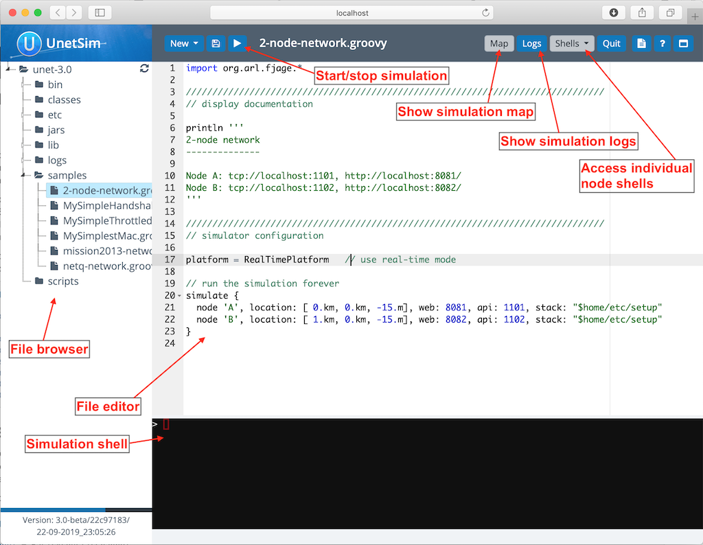
The IDE provides you with a fairly common 3-panel layout, with a file browser in the left panel, a simulation shell at the bottom, and a file editor occupying most of the window. At the top, you see several buttons. The key buttons to note are the
button that starts/stops simulations, the
Map
button that shows the current simulated nodes on a map, the 'Logs' button that allows you to view simulation logs, and a
Shells
dropdown that lists all the shells of simulated nodes. You can select any of the nodes from the list to connect to the shell of that node. The
Map
and
Shells
buttons are activated only once a simulation is running.
Load the
2-node-network.groovy
simulation script from the
samples
folder in the file editor. Then press
to run it.
You can either press the
button or type
sim.run 'samples/2-node-network.groovy'
to run the simulation from the simulation shell panel.
|
In the shell panel, you’ll see:
2-node network
--------------

Node A: tcp://localhost:1101, http://localhost:8081/
Node B: tcp://localhost:1102, http://localhost:8082/
To access node A shell, either control-click the URL for node A shell (displayed on the simulation shell) or select
Node A (232)
from the
Shells
dropdown menu. This will open the node A shell in a separate browser tab. Once you have access to the shells for your node, you are on familiar ground, as you have been working with numerous realtime simulations in previous chapters. Now, you can safely close the shell tab for now and go back to the IDE tab. The shell tab can be reopened anytime you want.
Next, try out the
Map
button, and you’ll see the 2 nodes in our simulation on a map:
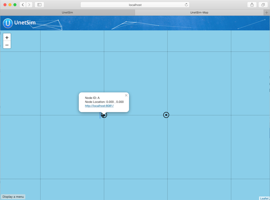
This map doesn’t look like much, with just 2 nodes 1 km apart on a blue background. The 2-node network simulation isn’t geolocated, so the map doesn’t have much to show. Let’s stop this simulation by pressing the
button, and start the
scripts/mission2013-network.groovy
simulation instead.
You can either press the
button or type
sim.stop
in the simulation shell panel to stop the currently running simulation.
|
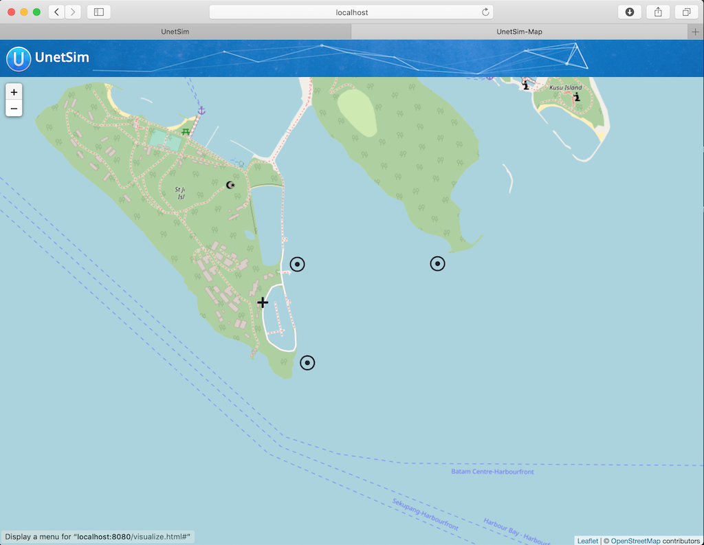
Now open the
Map
, and you’ll get a much nicer map of the network deployed in southern Singapore waters:
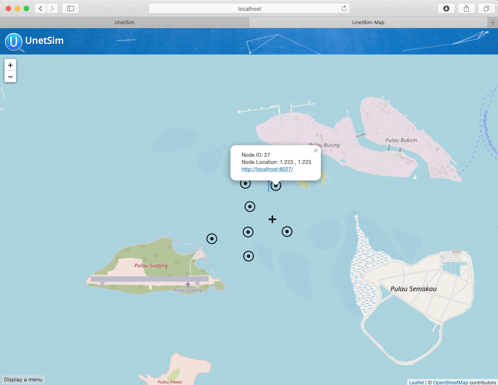
Clicking on each node shows some information about that node, and provides a link to opening that node’s shell (if it has a shell agent running). In case of mobile nodes ( Section 30.5 ), you’ll see the nodes moving on the map.
30.2. 2-node network
Now that we know how to use the IDE, let’s stop the mission2013 network simulation and reopen the 2-node network simulation in the file browser. Recall that we started off the previous section wanting to study the
2-node-network.groovy
simulation script in detail to see how it works. So let’s get down to it:
samples/2-node-network.groovy
:
import org.arl.fjage.*                                     (1)

///////////////////////////////////////////////////////////////////////////////
// display documentation

println '''                                                (2)
2-node network
--------------

Node A: tcp://localhost:1101, http://localhost:8081/
Node B: tcp://localhost:1102, http://localhost:8082/
'''

///////////////////////////////////////////////////////////////////////////////
// simulator configuration

platform = RealTimePlatform                                (3)

// run the simulation forever
simulate {                                                 (4)
  node 'A', location: [ 0.km, 0.km, -15.m], web: 8081, api: 1101, stack: "$home/etc/setup"
  node 'B', location: [ 1.km, 0.km, -15.m], web: 8082, api: 1102, stack: "$home/etc/setup"
}| 1 | Import classes needed in the simulation script. |
| 2 | Display documentation. |
| 3 | Tell the simulator that we want to run in realtime mode. |
| 4 | Describe the simulation specifying nodes names 'A' and 'B', their locations, web interface port numbers, API port numbers and the default network stack to load on each node. |
The simulation script is very simple. All it does is specify that we want to use the
RealTimePlatform
(since we want to run a realtime simulation), and then define the two nodes in the simulation. Node attributes such as node name, location, ports, and stack (agents to load) are specified when describing each node.
Let’s next take a look at the
setup.groovy
script that describes the stack to load on each node:
etc/setup.groovy
:
import org.arl.fjage.Agent

boolean loadAgentByClass(String name, String clazz) {        (1)
  try {
    container.add name, Class.forName(clazz).newInstance()
    return true
  } catch (Exception ex) {
    return false
  }
}

boolean loadAgentByClass(String name, String... clazzes) {   (2)
  for (String clazz: clazzes) {
    if (loadAgentByClass(name, clazz)) return true
  }
  return false
}

loadAgentByClass 'arp',       'org.arl.unet.addr.AddressResolution'
loadAgentByClass 'ranging',   'org.arl.unet.phy.Ranging'
loadAgentByClass 'mac',       'org.arl.unet.mac.CSMA'
loadAgentByClass 'uwlink',    'org.arl.unet.link.ECLink', 'org.arl.unet.link.ReliableLink' (3)
loadAgentByClass 'transport', 'org.arl.unet.transport.SWTransport'
loadAgentByClass 'router',    'org.arl.unet.net.Router'
loadAgentByClass 'rdp',       'org.arl.unet.net.RouteDiscoveryProtocol'
loadAgentByClass 'state',     'org.arl.unet.state.StateManager'

container.add 'remote',       new org.arl.unet.remote.RemoteControl(cwd: new File(home, 'scripts'), enable: false)
container.add 'bbmon', new org.arl.unet.bb.BasebandSignalMonitor(new File(home, 'logs/signals-0.txt').path, 64)| 1 | Helper function to load an agent given it’s class name. |
| 2 | Helper function to load an agent from a list of class names, picking the first available class. |
| 3 |
We use the second helper function to load
ECLink
if available (only premium stack), or
ReliableLink
as a fallback (available in basic stack).
|
While this script might look complicated, what it does is quite simple. It loads the standard agents in the network stack. The complicated bits in the script are mostly to handle errors, if certain agents are unavailable (e.g. agents from the premium stack). We could use a much simpler script to load the stack, if we wanted to avoid this complexity:
etc/setup.groovy
:
container.add 'arp',       new org.arl.unet.addr.AddressResolution()
container.add 'ranging',   new org.arl.unet.phy.Ranging()
container.add 'mac',       new org.arl.unet.mac.CSMA()
container.add 'uwlink',    new org.arl.unet.link.ReliableLink()
container.add 'transport', new org.arl.unet.transport.SWTransport()
container.add 'router',    new org.arl.unet.net.Router()
container.add 'rdp',       new org.arl.unet.net.RouteDiscoveryProtocol()
container.add 'state',     new org.arl.unet.state.StateManager()
container.add 'remote',    new org.arl.unet.remote.RemoteControl(cwd: new File(home, 'scripts'), enable: false)
container.add 'bbmon',     new org.arl.unet.bb.BasebandSignalMonitor(new File(home, 'logs/signals-0.txt').path, 64)
This script just loads all the standard agents in the basic stack.
If you wanted to customize the stack in the simulation, you could specify a different script to setup the stack, or provide a closure directly when defining the simulation:
simulate {
  node 'A', location: [ 0.km, 0.km, -15.m], web: 8081, api: 1101, stack: "$home/scripts/custom.groovy"
  node 'B', location: [ 1.km, 0.km, -15.m], web: 8082, api: 1102, stack: {
    // only load 3 agents on node B
    container.add 'arp',       new org.arl.unet.addr.AddressResolution()
    container.add 'mac',       new org.arl.unet.mac.CSMA()
    container.add 'uwlink',    new org.arl.unet.link.ReliableLink()
  }
}
Recall that in
Section 28.2
, we developed our own
EchoDaemon.groovy
agent. If we wanted to preload it in our 2-node network simulation, we can add
container.add 'echo', new EchoDaemon()
in the
custom.groovy
script or directly in the closure shown above.
|
30.3. Netiquette 3-node network
The
2-node-network.groovy
script defined 2 nodes that were 1 km apart, but were not geolocated. Recall from
Section 5.6
that specifying a node origin allows us to geolocate the nodes on a map. The
netq-network.groovy
simulation script does this:
samples/netq-network.groovy
:
import org.arl.fjage.RealTimePlatform

///////////////////////////////////////////////////////////////////////////////
// display documentation

println '''
Netiquette 3-node network
-------------------------

Node A: tcp://localhost:1101, http://localhost:8081/
Node B: tcp://localhost:1102, http://localhost:8082/
Node C: tcp://localhost:1103, http://localhost:8083/
'''

///////////////////////////////////////////////////////////////////////////////
// simulator configuration

platform = RealTimePlatform   // use real-time mode
origin = [1.216, 103.851]     (1)

simulate {
  node 'A', location: [121.m,  137.m, -10.m], web: 8081, api: 1101, stack: "$home/etc/setup"
  node 'B', location: [160.m, -232.m, -15.m], web: 8082, api: 1102, stack: "$home/etc/setup"
  node 'C', location: [651.m,  140.m,  -5.m], web: 8083, api: 1103, stack: "$home/etc/setup"
}| 1 |
The specified
origin
(latitude, longitude) applies to all nodes in the simulation.
|
Starting the simulation and opening the map shows the nodes on the map, since the origin allows the IDE to geolocate the nodes:
The
icon on the map marks the origin location.
30.4. Mission 2013 network
The simulation script is written in Groovy, so you can include complex logic in the script , if you wish. From this perspective, the
mission2013-network.groovy
script is instructive to look at:
samples/mission2013-network.groovy
:
import org.arl.fjage.RealTimePlatform
import org.arl.unet.sim.channels.Mission2013a

///////////////////////////////////////////////////////////////////////////////
// display documentation

println '''
MISSION 2013 network
--------------------
'''
Mission2013a.nodes.each { addr ->
  println "Node $addr: tcp://localhost:${1100+addr}, http://localhost:${8000+addr}/"
}

///////////////////////////////////////////////////////////////////////////////
// simulator configuration

platform = RealTimePlatform   // use real-time mode
channel = [ model: Mission2013a ]                          (1)
origin = [1.217, 103.743]

simulate {
  Mission2013a.nodes.each { addr ->                        (2)
    node "$addr", location: Mission2013a.nodeLocation[addr], web: 8000+addr, api: 1100+addr, stack: "$home/etc/setup"
  }
}| 1 |
The
channel
property of the simulation enables us to define details of the simulated physical channel for the network. We will learn more about simulating channels in
Chapter 32
.
|
| 2 |
Nodes can be created programatically by iterating over the list of nodes defined in the
Mission2013a
class.
|
The
Mission2013a
class contains information about the MISSION 2013 experiment. The
mission2013-network.groovy
simulation script uses this information to create simulated nodes at the correct locations, and to define a channel model based on measurements during that experiment.
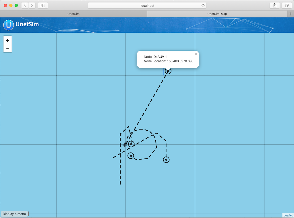
30.5. Node mobility
Nodes in a simulation may be mobile (e.g. autonomous underwater vehicles). Such nodes have motion models associated with them, to provide appropriate mobility during the simulation:
// AUV-1 moving in a straight line at constant speed
def n1 = node 'AUV-1', location: [0, 0, 0], mobility: true
n1.motionModel = [speed: 1.mps, heading: 30.deg]

// AUV-2 moving in a circle (constant speed, constant turn rate)
def n2 = node 'AUV-2', location: [0, 0, 0], mobility: true
n2.motionModel = [speed: 1.mps, turnRate: 1.dps]
We can also define more complex motion models:
// AUV-3 moving in a lawnmower pattern
def n3 = node 'AUV-3', location: [-20.m, -150.m, 0], heading: 0.deg, mobility: true
n3.motionModel = MotionModel.lawnmower(speed: 1.mps, leg: 200.m, spacing: 20.m, legs: 10)

// AUV-4 moving as defined below, using time or duration
def n4 = node 'AUV-4', location: [-50.m, -50.m, 0], mobility: true
n4.motionModel = [
  [time:     0.minutes, heading:  60.deg, speed:       1.mps],
  [time:     3.minutes, turnRate:  2.dps, diveRate:  0.1.mps],
  [time:     4.minutes, turnRate:  0.dps, diveRate:    0.mps],
  [time:     7.minutes, turnRate:  2.dps                    ],
  [time:     8.minutes, turnRate:  0.dps                    ],
  [duration: 3.minutes, turnRate:  2.dps, diveRate: -0.1.mps],
  [duration: 1.minute,  turnRate:  0.dps, diveRate:    0.mps]
]
We can even combine motion models:
def n5 = node 'AUV-5', location: [-20.m, -150.m, 0], heading: 0.deg, mobility: true

// dive to 30m before starting survey
n5.motionModel = [
  [duration: 5.minutes, speed: 1.mps, diveRate: 0.1.mps],
  [diveRate: 0.mps]
]

// then do a lawnmower survey
n5.motionModel += MotionModel.lawnmower(speed: 1.mps, leg: 200.m, spacing: 20.m, legs: 10)

// finally, come back to the surface and stop
n5.motionModel += [
  [duration: 5.minutes, speed: 1.mps, diveRate: -0.1.mps],
  [diveRate: 0.mps, speed: 0.mps]
]
Let’s put AUVs 1-4 together into a single simulation script:
auv-network.groovy
import org.arl.fjage.RealTimePlatform
import org.arl.unet.sim.MotionModel

platform = RealTimePlatform

simulate {
    def n1 = node 'AUV-1', location: [0, 0, 0], mobility: true
    n1.motionModel = [speed: 1.mps, heading: 30.deg]
    def n2 = node 'AUV-2', location: [0, 0, 0], mobility: true
    n2.motionModel = [speed: 1.mps, turnRate: 1.dps]
    def n3 = node 'AUV-3', location: [-20.m, -150.m, 0], heading: 0.deg, mobility: true
    n3.motionModel = MotionModel.lawnmower(speed: 1.mps, leg: 200.m, spacing: 20.m, legs: 10)
    def n4 = node 'AUV-4', location: [-50.m, -50.m, 0], mobility: true
    n4.motionModel = [
        [time:     0.minutes, heading:  60.deg, speed:       1.mps],
        [time:     3.minutes, turnRate:  2.dps, diveRate:  0.1.mps],
        [time:     4.minutes, turnRate:  0.dps, diveRate:    0.mps],
        [time:     7.minutes, turnRate:  2.dps                    ],
        [time:     8.minutes, turnRate:  0.dps                    ],
        [duration: 3.minutes, turnRate:  2.dps, diveRate: -0.1.mps],
        [duration: 1.minute,  turnRate:  0.dps, diveRate:    0.mps]
    ]
}
Save this
auv-network.groovy
in your
scripts
folder and run it. Open the map, and watch your AUV nodes move!